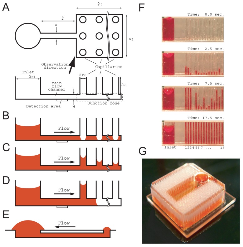
Figure 1.
Schematic illustrations of a fluidic chip including a passive pump composed of an integrated vertical capillary array and its suction profile. (A) Definitions of position and the notations are summarized in the top and side view illustrations. (B) Fluid can propagate in the area of the main flow channel and the junction zone except at the bottoms of the capillaries when d < rc. (C) A quasi-steady flow is realized after the B stage. (D) No quasi-steady flow is realized if d < rc is not satisfied. (E) Comparison with a surface tension pump. (F) Time-series imagery of the suction profile of 4-mm-long capillaries in a 3 × 5 arrangement in a square lattice and 2 mm apart; d, rc, and ri were 0.05, 0.2, and 1.5 mm, respectively. (G) A fluidic chip with a highly integrated vertical capillary array provided a large volume sample for actual sensor application. The main flow channel (not shown) was surrounded by capillaries and an inlet to realize a large flow volume on a small footprint. Sample fluid injected into the inlet propagates in the main channel and branches to the right and left junction zones. The capillaries were arranged in a hexagonal lattice and were 0.35 mm apart. There were 816 capillaries, and the capillary length, d, rc, and ri were 4, 0.05, 0.14 and 1.5 mm, respectively. Image obtained after several refill operations.

