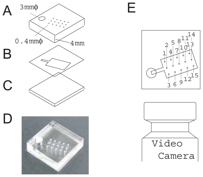
Figure 2.
Structure of fluidic chip (A–D) and setup for flow rate measurement (E). An inlet (3 mm diameter) and a vertical capillary (0.4 mm diameter) array were opened in the thick (4 mm) acrylic resin plate (A). 15 capillaries were arranged in a square lattice and 2 mm apart. A flow channel was opened in a thin (0.05 mm-thick) two-sided adhesive film (B). The bottom of the device was a 1 mm-thick acrylic resin plate (C). The assembled flow device is shown in (D). Liquid fronts in the inlet and capillaries were observed and recorded from the side of the fluidic chip using a video camera. All the capillaries can be observed without any overlaps from an oblique direction. Individual capillaries are identified by the numbers shown in (E). These numbers are common throughout this paper.

