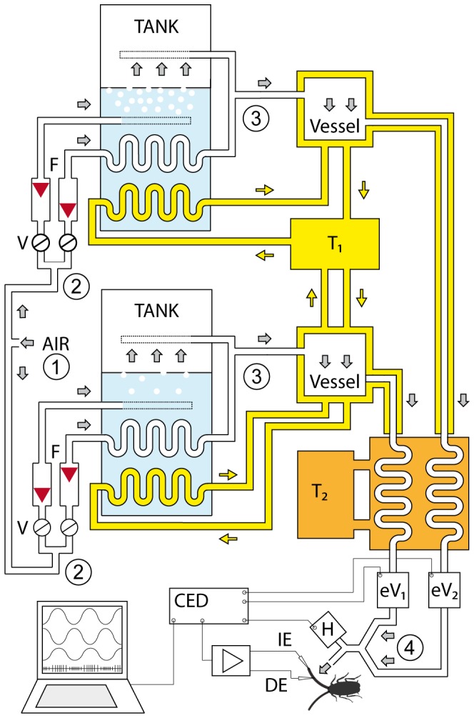
Figure 3. Delivery system for sinusoidal humidity modulation.

Compressed air was divided at 1 into two air streams to be set at different water vapor pressure values. Each stream was further split into two substreams (at 2) and their flow rates adjusted by needle valves (V) and monitored continuously by flow meters (F) before passing through a tank of water at constant depth and temperature (42°C). One substream bubbled out through many holes in a polyethylene tubing in a tank of ion-exchange water at constant 42°C. Temperature was controlled by thermostat 1 (T1). The second substream was conducted through the spiral tube in the same tank but remained dry when it was also warmed to 42°C. After emerging from the tank, the two substreams were combined in a single stream (at 3) variable in water vapor content from dry to almost saturated. Homogeneity of mixture was enhanced by a 2-l series connected vessel. Water-jacket insulation is shown. The temperature of the two air streams was then set at given temperature levels by driving them through a thermostatically controlled heat exchanger (T2). After passing through electrical proportional valves (eV1, eV2), the air streams were combined to a single stream (at 4). The vapor pressure of his stream was sinusoidally modulated by mixing the two streams in a ratio determined by the proportional valves by means of the output sequencer function of the data acquisition software (Spike2; Cambridge Electronic Design, CED, Cambridge, UK). By 180° phase shifting of the control voltages of the electrical proportional valves, the flow rate of the combined air stream was held constant. The antenna was placed at the outlet of the stimulus air stream, the recording or different electrode (DE) inserted at the base of the hygroreceptive sensillum and the reference or indifferent electrode (IE) into the tip of the antenna. Humidity stimulation was measured by a UV-absorption hygrometer (H).
