
Figure 12.
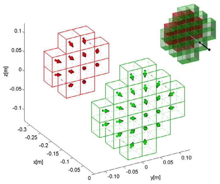
Plot showing the optimal geometry and magnetization directions for a 36 element 3D Halbach pull array (with the same volume as the benchmark pull magnet shown in Figure 5). Each element is a cube with every side measuring 3.816 cm. The two layers of the Halbach array along the x-axis (front layer shown in green, rear in red) are shown apart to better visualize the magnetization directions. The overall formation of the array is shown at top right where the two layers are right next to each other and the optimization point and resulting force are shown by the black dot and arrow. The 2-layer “pyramid” shape is again optimal because the most effective elements are the ones closest to the optimization point. Also as before, the magnetization directions “fan in”, like in Figure 8, to push out and focus the magnetic field to better include the optimization point.