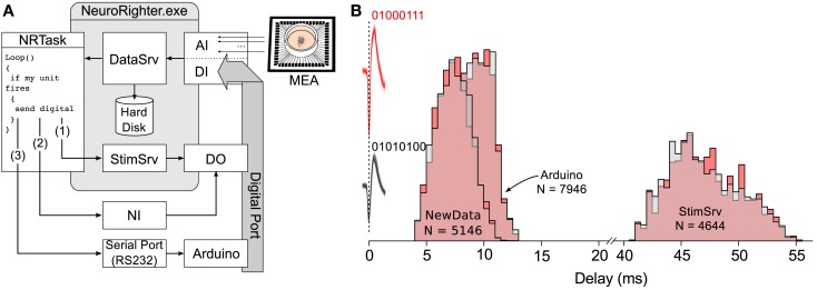
Figure 4.
Estimated loop times for bi-directional communication using different hardware configurations. (A) Schematic of experiment used to test reaction delays for different real-time hardware options. Spikes detected and sorted from 59-channel planar electrode array were passed to the real-time plugin. The plugin determined if a spike originated from one of two units of interest. In the case that a spike was produced by one of the two units, the plugin triggered the generation of a digital word encoding the detected unit using either StimSrv, unbuffered digital output triggered by a NewData event, or an Arduino board. Digital signals were then, recorded though NeuroRighter’s digital input port. (B) Normalized histogram of time delays from spikes produced by the two units of interest (action potential waveforms are shown in pink and gray and occur at 0 ms) to the recorded digital signals produced by the plugin to encode the units (01000111 or 01010100). Delay histograms are shown for each unit (pink and gray) and the three different hardware options. N is the number of spikes recorded for each hardware option.

