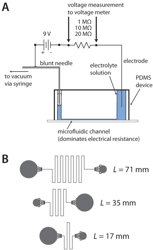
Figure 1.

A) System used for conductivity measurements. Electrical resistors of 1, 10, or 20 MΩ, in series with the microchannel, were interchanged based on the length and depth of the microchannel. B) Design of the fluidic channels, or fluidic resistors, used to make the conductivity measurements. Channel lengths of 17, 35, and 71 mm were fabricated with channel depths of 33, 52, and 78 μm, resulting in nine different values of fluidic resistance for this study. Fluidic reservoirs (gray) were interfaced to channels using monolithic debris filters, which had negligible effect on fluidic resistance values.
