Figure 3.
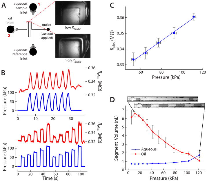
A) Channel layout of droplet generating microfluidic device. The inset images show the variable resistor region at low Rfluidic (upper image) and high Rfluidic (lower image) after pressure is applied. B) Different pressure waveforms (blue traces) were applied to the variable resistor, and Relec of the channel (red traces) varied similarly, as expected. C) A linear relationship was observed between the pressures applied to the variable resistor and the oil channel’s Relec value. D) Plot of segment volume of the oil and aqueous phases over a range of pressures applied to the variable resistor. Increasing pressure (i.e. increasing Rfluidic of the oil channel) resulted in increased aqueous droplet volume and decreased oil segment volume between droplets, providing dynamic control of droplet size and spacing. Inset images show examples of droplet sizes and spacing. Microchannels in all inset images (parts A and D) are 100 μm wide.

