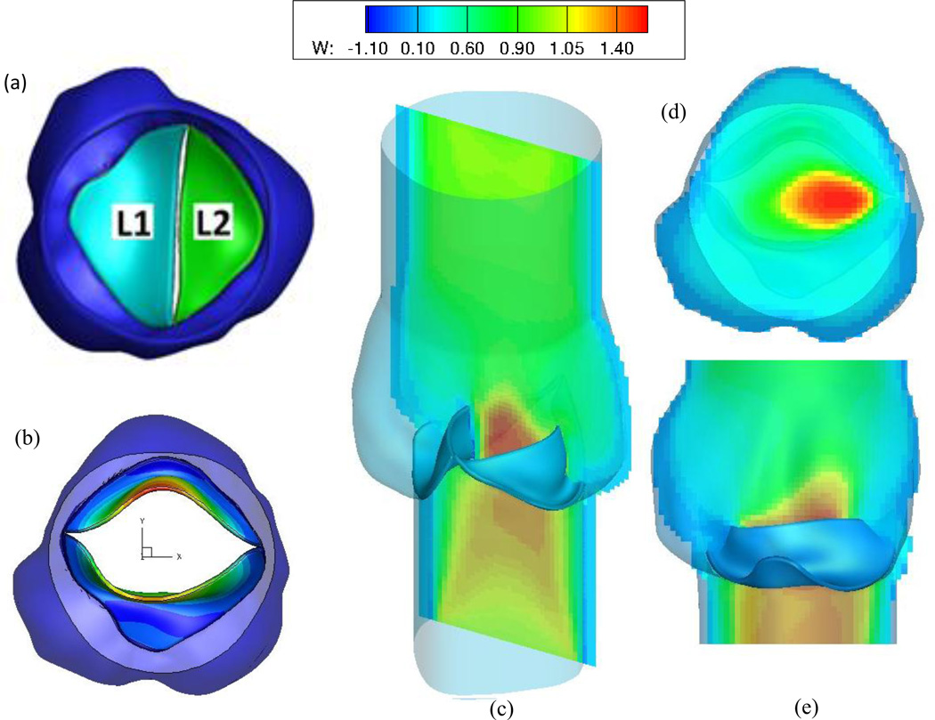
Figure 7.
Preliminary results for a full FSI simulation of a patient-specific bicuspid aortic valve. (a) The original, closed configuration of the type II BAV plus aortic root, where L1 is adjacent to the non- and right-coronary sinuses, while L2 is attached to the left-coronary sinus. (b) The fully open position of the BAV, with contours of displacement. Note the relatively small EOA. (c) Axial flow contours (d) Axial flow at a slice within the aortic sinus (e) Flow along the center slice of the geometry, between the two open leaflets. Note the skewing of the jet, toward the left coronary sinus region.

