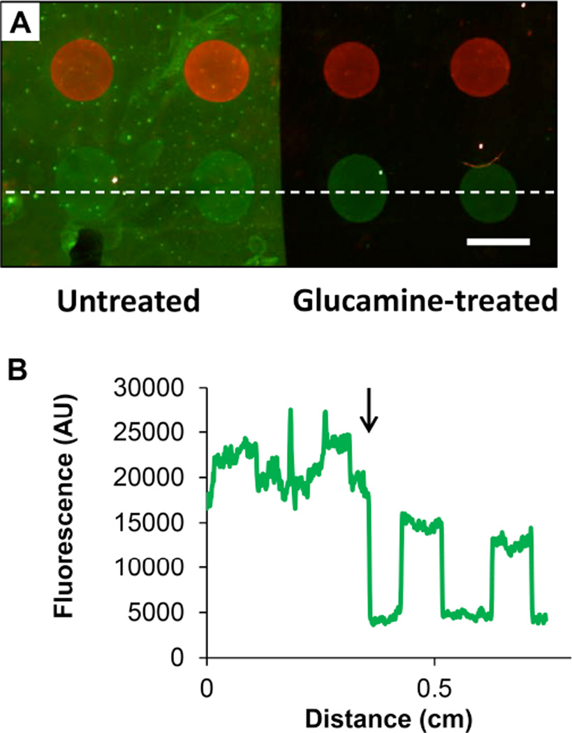
Figure 2.
(A) Merged fluorescence micrograph of an oligonucleotide array of Probes 1 and 2 spotted onto a glass slide coated with a PEI/PVDMA film 4.5 bilayers thick. Prior to hybridization, the right half of the array was selectively treated with glucamine to produce a non-fouling surface, while the left half of the array was left untreated (i.e. azlactonefunctionalized). The array was hybridized using an aqueous solution containing a mixture of fluorescein-labeled Complement 1 (green), fluorescein-labeled BSA (green), and Cy3-labeled Complement 2 (red) prior to imaging (see text). Scale bar is 1 mm. (B) Line intensity profile taken from the bottom row of features of the array in (A) (in a location near the dotted white line) for the green channel only; the approximate location of the boundary between the glucamine-treated region of the array (right) and untreated region (left) is indicated in this plot by the black arrow.

