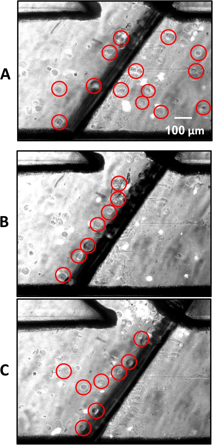
Figure 5.
Separation of MCF-7 (encircled) and HCT-116 (fluorescent). The circles are used to mark MCF-7. (a) Shows flow of HCT-116 and MCF-6 through the main channel prior to activation of the AC electric field. (b) Reflects flow through the channel after activation at 3.2 MHz where undyed cells (MCF-7) are aligned parallel to the electrode (dark region) and are being deflected into the side channel while the HCT-116 path is unaltered. (c) Shows a low specificity scenario of separation between the MCF-7 and HCT-116 with both being deflected into the side channel under a frequency of 2 MHz.

