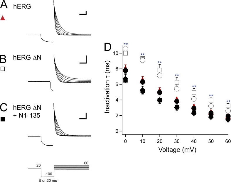
Figure 6.
eag domain regulation of hERG inactivation rate. (A–C) Sample two-electrode voltage-clamp recordings to isolate inactivating currents from hERG (A), hERG ΔN (B), and hERG ΔN plus N1–135 (C) using the three-pulse protocol shown. The duration of the second pulse was 20 or 5 ms based on the construct so that minimal deactivation occurred during this step. Calibration bar, 2 µA and 10 ms. (D) Plot of the time constants (τ) of inactivation derived from single-exponential fits to the current decay in A–C and from hERG Δeag (open circle), hERG Δeag plus N1–135 (closed circle), and hERG ΔN plus N1–354 (closed diamond). Error bars are the SEM and are within the points if not visible. n ≥ 9 for each construct. **, P < 0.01 versus hERG.

