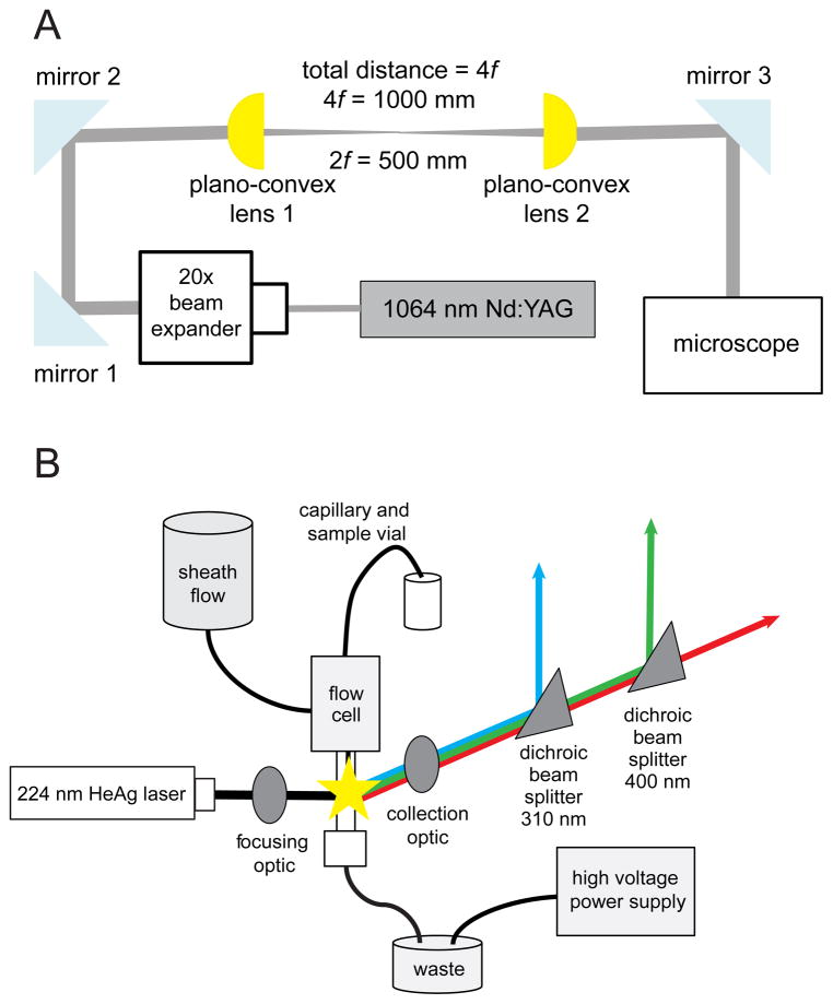
Figure 1.
The OT and MC-CE-LINF instrument design (both being interfaced to the same sample stage on the microscope). (A) Schematic of the optical trap. Emission from the Nd:YAG laser is expanded by a 20× beam expander to fill the back aperture of the objective. The beam is directed into a pair of plano-convex lenses, which act to steer and parfocalize the beam. The beam is directed in the epi-fluorescence port of a microscope and a dichroic mirror directs it into the objective. (B) Schematic for the MC-CE-LINF instrument. Emission from the HeAg laser is focused 0.5–1 mm below the capillary outlet. Fluorescence is collected orthogonal to excitation by an objective, which collimates and directs the emission to two dichroic beam splitters. The beam splitters separate the emission into three wavelength ranges: 250–310 nm (PMT blue), 310–400 nm (PMT green), and 400 nm and above (PMT red), and a photomultiplier tube detector quantifies the emission intensity for each wavelength range.

