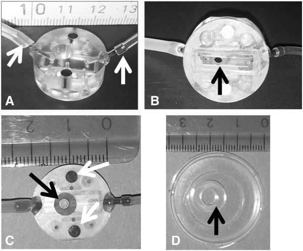
Figure 1.
The in vitro flow chamber. The flow chamber is shown from the side (A), from the base (B) and from the top (C). White arrows in panel A show the inlet and outlet tubes. Black arrows in panels B and C show the field of view. A rectangle within the thin silicon mat visible in panel B surrounds the inflow and the outflow and restricts medium flow to a small chamber 2 mm wide and 0.25 mm high. White arrows in panel C show the magnets embedded into the flow chamber to fix the chamber via a metal ring opposed on the base of the culture dish. The cloning ring shown with a diameter of 0.6 cm in image D restricts the surface area of brain endothelial cells to 0.28 cm2. Scale is in cm.

