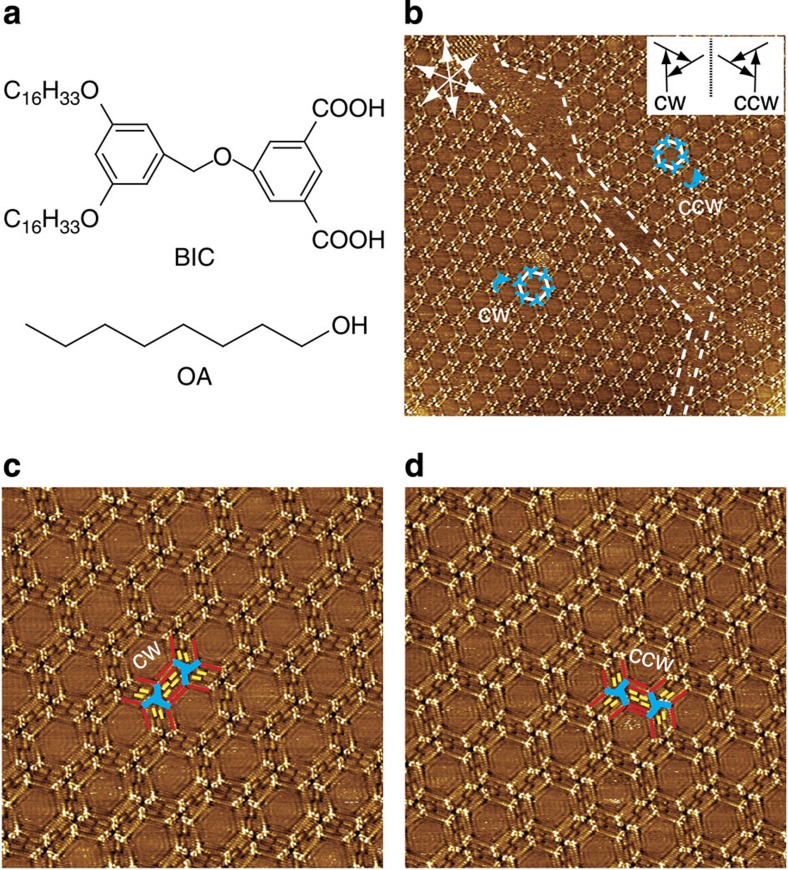
Figure 1. Self-assemblies of BIC at the OA/HOPG interfaces.
(a) Chemical structures of BIC and OA. (b) Large-scale STM image (93 × 93 nm2, I=0.205 nA, Vbias=0.900 V) of BIC monolayer at the OA/HOPG interface. The dotted lines indicate domain boundaries. The white hexagons indicate the hexagonal units in BIC assembly. The blue windmills and arrows indicate the BIC trimers and their rotational directions, respectively. The white arrows indicate the substrate lattice of HOPG. Inset, CW and CCW rotation of a BIC trimer is defined by the vectors from the benzene ring attached with the alkoxy chains to the isophthalic acid moiety. (c) High-resolution STM image (38 × 38 nm2, I=0.066 nA, Vbias=0.912 V) of the CW network. (d) High-resolution STM image (40 × 40 nm2, I=0.065 nA, Vbias=0.900 V) of the CCW network. The blue, red and yellow lines in c and d outline the bright aromatic cores, the alkoxy chains in BIC, and the alkyl chains in the solvent, respectively.

