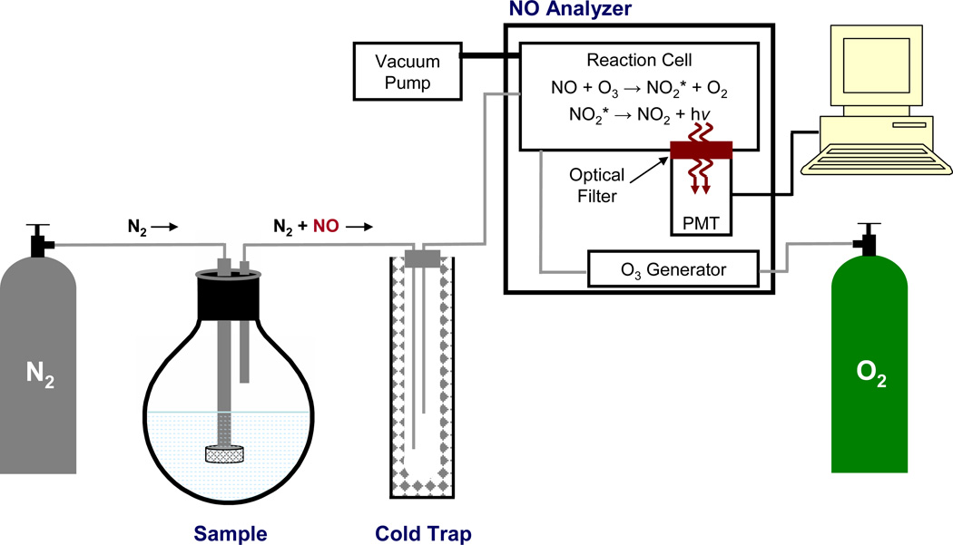
Figure 2.
Schematic diagram of a chemiluminescence-based nitric oxide analyzer. An intert gas (e.g., nitrogen (N2)) is used to both deoxygenate sample buffer and carry NO from the sample flask though a cold trap (to remove water vapor) into a reaction cell within the nitric oxide analyzer. In the reaction cell, nitric oxide (NO) reacts with ozone (O3) to form excited-state nitrogen dioxide (NO2*), which emits a photon (i.e., chemiluminescence) upon its relaxation to the ground state (NO2). Emitted light passes through an optical filter and is detected by a photomultiplier tube (PMT).

