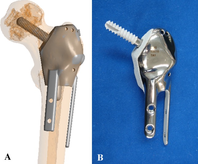
Fig. 3A–B.

(A) A diagram shows the preoperative position of the CAD prosthesis in Patient 5 with left proximal femur Grade 2 chondrosarcoma and multiplanar osteotomies. Reprinted with permission from Wong KC, Kumta SM, Tse LF, Ng EW, Lee KS. Image fusion for computer-assisted tumor surgery (CATS). In: Ukimura O, ed. Image Fusion. InTech; 2011. Available at: http://cdn.intechopen.com/pdfs/12998/InTech-Image_fusion_for_computer_assisted_tumor_surgery_cats_.pdf. Accessed June 27, 2012. (B) A photograph shows the anterior view of the actual CAD prosthesis. Two extracortical plates and screws are used for fixation of the femoral shaft while one screw is used for fixation of the femoral head and neck. All implant junctions in contact with host bone are coated with HA (white color).
