
Figure 1.
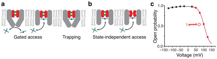
Block mechanism with two gate locations. (a, b) MthK pore cartoons illustrating gated access and blocker trapping (a) versus state-independent access of blockers (b). Selectivity filter is red with two K+ ions bound (green). Inner-pore helices (grey) may form a bundle-crossing gate. (c) Mean open probability (Po) measurements for MthK in symmetric 200 mM K+ (n = 3–8, mean ± S.D., error bars smaller than symbols). Inactivation gating (50 to 125 mV, red) is described by voltage-dependent transitions between one open (O) and one inactivated (I) state and was fit to a Boltzmann function (red line, Equation 1) with Pomax = 0.994 ± 0.004, z = 1.44 ± 0.02, and V½ = 103.3 ± 0.2 mV (Supplementary Figure 1A). The black line has no theoretical meaning.