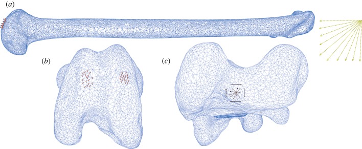
Figure 4.

Load parameters and boundary conditions for FEA of the Senegal bushbaby (Galago senegalensis) femur. (a) Femur in lateral view. Yellow arrows indicate changing load vector incrementally from parallel to the bone's longest principal axis (compressive loading regime) to perpendicular (bending loading regime), according to the combined compressive–bending model. (b) Markers indicate encastre boundary conditions constraining distal condyles in three directions. (c) Kinematic coupling constraint between a central reference point and 10 nodes forming the load surface, to which a torsional moment is applied.
