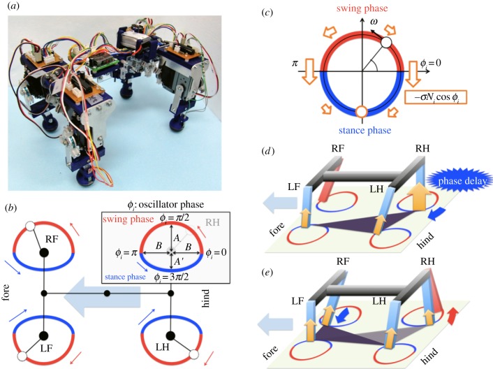
Figure 2.
(a) Constructed robot. (b) Target trajectories. Boxed diagram illustrates target trajectory of RH leg on the basis of the oscillator phase. (c) Dynamics in the phase oscillator depending on local sensory feedback. Phase is pulled towards 3π/2 based on the local sensory feedback (indicated by the arrows). (d,e) Physical effect of the local sensory feedback. (d) Phase delay introduced by  allows another leg to enter the stance phase. (e) As the other leg begins to support the body, the feedback effect on the corresponding leg decreases, allowing it to enter the swing phase.

