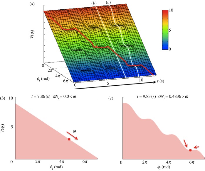
Figure 7.
Dynamical structure underlying a steady walking pattern generated by the proposed control scheme. (a) Potential function V(ϕi) obtained from the dynamics of the proposed model. Ni affects the V(ϕi) curve. (b) When  in the swing phase, V(ϕi) has a smooth slope. (c) When
  in the stance phase, V(ϕi) has a varying slope, and some local minima in which the phase converges to each point and remains there. The red line in (a) represents the trajectory of the phase ϕi.

