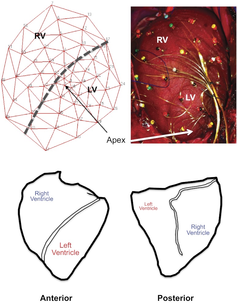
Fig. 1.
Configuration of the 56-electrode sock and porcine ventricular anatomy. A: schematic representation of the sock electrode including relative positions of the right ventricle (RV) and left ventricle (LV) (left). After placement on porcine ventricles, the actual 56-electrode sock is shown, with relative position of the RV and LV (right). B: relationship of the porcine RV and LV in the anterior and posterior orientation (left and right, respectively).

