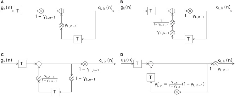
Figure A1.
Illustration of the equivalence of the digital filter (14) (Figure 3) to the count function as in (13). (A) Block diagram of the DIF model’s long-term memory filter of Figure 3 and (14) with input signal gk(n) and output signal cL,k(n). (B) Block diagram of a filter equivalent to (A), where the multiplier (1 − γL,n − 1) has been moved to the right. (C) Block diagram of a filter equivalent to (B), where the multiplier (1 − γL,n − 1) has been moved even further to the right. (D) Block diagram of a filter equivalent to (C), where the multiplier γL,n − 1/(1 − γL,n − 1) has been moved to the right of the delay unit in the lower branch.

