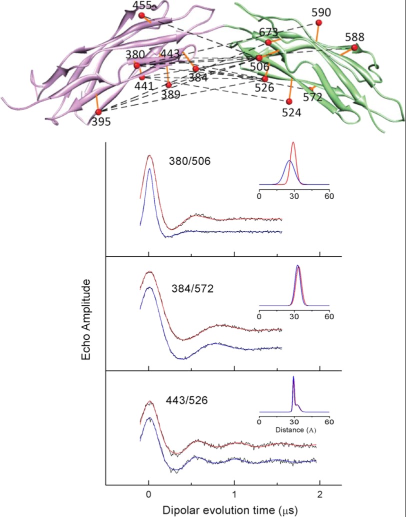
FIGURE 9.
Pairs of sites selected for site-directed spin labeling in CBD12 and DEER spectra for three pairs of sites. The ribbon diagram of for the CBD1 domain is shown in purple (coordinates were from PDB 2DPK), and the ribbon diagram for the CBD2 domain is shown in green (coordinates were from PDB 2QVM) in the upper panel. The sites where pairs of R1 spin-labeled side chains were incorporated are shown as solid orange spheres connected by dashed lines. The spheres for each selected residue are centered at the coordinates of the average position of the midpoint of the N-O bond of the nitroxide, which was calculated as described under “Experimental Procedures.” The DEER data for three selected pairs of sites are shown as solid black lines in the lower panel. The fits to the DEER data are shown as solid blue lines (no bound Ca2+) and solid red lines (saturating level of bound Ca2+). The average distances and widths of the distance distributions are shown in the insets to each DEER data set in Å. The parameters from fitting the DEER data for all these three sites and those from the remaining sites shown in Fig. 10 in the presence of a saturating concentration of Ca2+ and with no bound Ca2+ are listed in Table 1.

