Abstract
Tongue drive system (TDS) is a new wireless assistive technology (AT) for the mobility impaired population. It provides users with the ability to drive powered wheelchairs (PWC) and access computers using their unconstrained tongue motion. Migration of the TDS processing unit and user interface platform from a bulky personal computer to a smartphone (iPhone) has significantly facilitated its usage by turning it into a true wireless and wearable AT. After implementation of the necessary interfacing hardware and software to allow the smartphone to act as a bridge between the TDS and PWC, the wheelchair navigation performance and associated learning was evaluated in nine able-bodied subjects in five sessions over a 5-week period. Subjects wore magnetic tongue studs over the duration of the study and drove the PWC in an obstacle course with their tongue using three different navigation strategies; namely unlatched, latched, and semiproportional. Qualitative aspects of using the TDS–iPhone–PWC interface were also evaluated via a five-point Likert scale questionnaire. Subjects showed more than 20% improvement in the overall completion time between the first and second sessions, and maintained a modest improvement of ~9% per session over the following three sessions.
Keywords: Assistive technologies, brain–tongue–computer interfacing, environment control, quadriplegia, smartphones, tongue piercing, wheeled mobility
I. Introduction
TONGUE drive system (TDS) is a wireless and wearable assistive technology (AT) for individuals with high-level paralysis. It allows them to use their unrestricted tongue motion to control many devices in their environments. There are various ATs, such as sip-and-puff, eye trackers, head arrays, electromyography switches, and voice recognition systems already available. These devices allow people with high-level spinal cord injuries (SCI) or other causes of upper limb paralysis gain some independence in their daily lives [1], [2]. For driving an electric-powered wheelchair (PWC), for instance, sip-and-puff is one of the most popular ATs [3]. It is affordable and simple. However, it offers only a limited number of commands and requires diaphragm control which may not be possible in some patients. Researchers have come up with alternatives such as eye controller based on electrooculography to navigate wheelchairs [4]. Other eye trackers based on pupil movement and infrared reflections have also been used to control a computer or a remote vehicle driving control [5]–[8]. There are brain computer interfaces (BCI) based on electroencephalography that are under development to access computers and more recently have been applied to PWCs as well [9]–[11]. Electromyography has also been utilized to access a computer or navigate a PWC [12], [13]. Tongue-operated ATs have also been reported for computer or PWC applications [14], [15].
However, very few devices can be effectively used to both access a computer and drive a PWC in unified, wireless, unobtrusive, and wearable form. Therefore, depending on the environments and tasks that they want to accomplish, users rely on multiple ATs and inevitably require assistance from family members or caregivers to switch from one to another. There is a need for more effective multifunctional ATs that can offer a higher degree of independence [16]–[18].
Our prior work mainly focused on the use of the TDS to control mouse cursor on a desktop PC or to navigate a PWC by running a sensor signal processing (SSP) algorithm and graphical user interface (GUI) on a laptop PC [19], [20]. Human subject trials on both able-bodied subjects and those with high-level SCI demonstrated that the TDS can be a substitute for a mouse or joystick to access computers and control PWCs, respectively [21]–[23].
A few practical limitations were also discovered in regard to the ease of use, safety, and appearance, particularly for outdoor mobile conditions. First, the laptop had to be placed in front of the novice users on a lap tray to provide them with visual feedback. However, the screen was obstructing the users' field of view, making it difficult for them to see nearby short objects. Second, the laptop was vulnerable to falls, liquid spillage, and humidity. It also limited the placement of additional padding, sometimes needed for postural adjustments and proper positioning of the users' legs and arms. It was necessary to make the interface between the TDS and PWCs considerably more compact, portable, unobtrusive, and robust.
Instead of designing dedicated hardware, which could end up being very time consuming and costly, we took advantage of the rapidly advancing smartphone technology by migrating both the SSP algorithm and GUI from PC to a smartphone. Besides its functionality as a phone, which is a measure of safety for those with severe disabilities to seek help in emergency situations, the new smartphones also have a host of built-in wireless connectivity options, such as Bluetooth and Wi-Fi, which can be utilized to connect the TDS to a growing list of networked devices in the users' home, office, and even outdoors environments.
In recent years, the smartphone technology is being considered for emerging applications in medicine, some of which take advantage of the phone's built-in sensors while others interface with external modules and utilize the smartphone as a processing, display, and communication platform [24]–[26]. Considering its powerful processor, high-resolution display, and popularity, we chose the iPhone/iPod (Apple Inc., Cupertino, CA) as our first smartphone platform to implement the TDS–smartphone–PWC interface [27]. We had already developed the TDS–iPhone interface, and preliminary tested it via a simple phone call application [28]. To connect the TDS to the iPhone via its serial port, a custom wireless adapter was designed in the form of a dongle, mounted along with the iPhone below the PWC display using an off-the-shelf holder without blocking the users' field of view, as shown in Fig. 2(a).
Fig. 2.
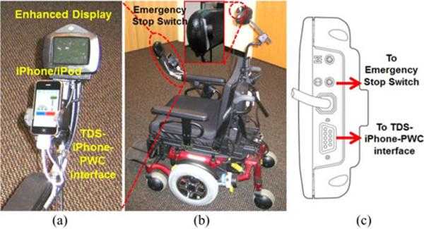
Connecting TDS to PWC via iPhone: (a) standard PWC controller for a Pride Q6000 PWC, known as the Enhanced Display, was connected to the TDS–iPhone–PWC interface via its DB-9 connector. (b) All the necessary components to drive the PWC, including a head-operated emergency stop switch, mounted on the PWC headrest, as a safety measure. (c) Utilized connections at the bottom of the Enhanced Display.
In the following section, we present the architecture of the TDS–iPhone–PWC interface, shown in Fig. 2, mounted on a Pride Q6000 (Pride Mobility Products, Exeter, PA) PWC. Section III describes the performance evaluation through a medium-term human subject trial, which included tongue piercing, a recovery period, and five PWC driving sessions using three different PWC control strategies. In Section IV, we analyze the experimental results in terms of quantified learning effects and a few subjective measures, followed by the concluding remarks.
II. System Architecture
A. TDS–iPhone–PWC Overview
Fig. 1 shows the operating diagram between TDS, iPhone, and PWC. In order to use the TDS on a regular basis, the user needs to wear the TDS headset and have a magnetic tracer semipermanently attached to the superior surface of the tongue. A possible solution that was adopted in our experiments is using a titanium tongue barbell with a ⊘4.8 mm × 1.5 mm rare earth magnet (K&J Magnetics, Jamison, PA) completely encased within the ellipsoid shaped upper ball (⊘8 mm × 3.5 mm). A 12 gauge post with a length of 12–21 mm, depending on the thickness of the tongue and comfort of the subject, was laser welded to the upper ball, forming a barbell-shaped tongue stud with a smaller spherical ball screwing onto the lower end. When the user moved the tongue, the magnetic tracer moved with it and changed the magnetic field distribution inside and around the mouth, which was captured by four 3-axial magnetic sensors mounted bilaterally, two on each side of the TDS headset [21]. This information was then used by the SSP algorithm to indicate the tongue position [19].
Fig. 1.
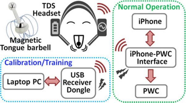
TDS–iPhone–PWC operating diagram: TDS headset communicates with a PC through a wireless USB dongle during calibration and training steps. For normal operation, the training results are wirelessly transferred from the PC to the iPhone via the TDS–iPhone–PWC interface, through which the iPhone also receives magnetic sensor raw data from the TDS headset.
To begin using the TDS, users need to calibrate the system to suppress the electromagnetic interference (EMI), and train the TDS by defining the desired tongue positions in their mouth that they want to associate with up to six independent commands, as explained in [23]. The TDS also detects the tongue resting position, which is always associated with the neutral command. In the current TDS prototype, calibration and training steps are conducted on a laptop PC. During calibration and training, the TDS headset wirelessly transmits the magnetic sensor outputs to the PC via a USB transceiver dongle. The PC generates a user-specific calibration/training package, which is wirelessly transferred to the iPhone from the USB dongle to the TDS–iPhone–PWC interface. Once the iPhone acknowledges the receipt of the calibration/training package, the TDS can directly send the magnetic sensors' raw data to the iPhone to begin the normal operation of the system, as shown in Fig. 1. Using the calibration/training package, the SSP algorithm running on the iPhone suppresses the EMI in the incoming data and translates them into user-defined commands, which are delivered to the PWC and also displayed on the iPhone screen to provide the user with visual feedback.
B. TDS–iPhone–PWC Hardware
The TDS–iPhone–PWC prototype is shown in Fig. 3. The TDS headset in Fig. 2(a) consists of an adjustable headgear with four 3-axial magnetoresistive sensors (HMC1043, Honeywell, Plymouth, MN), two on each side, held by a pair of goosenecks near the users' cheeks [see Fig. 2(d)]. Sensors are connected to a wireless control unit on top of the headset [see Fig. 2(b)], which includes sensor signal conditioning circuitry, a system-on-chip microcontroller with a built-in 2.4-GHz RF transceiver (CC2510, Texas Instruments, Dallas TX), a surface-mount antenna, a pair of AAA rechargeable batteries (850 mAh each), and power management circuitry.
Fig. 3.
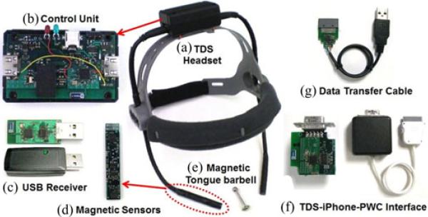
TDS–iPhone–PWC hardware components consisting of (a) TDS headset, (b) wireless control unit, (c) wireless USB transceiver dongle, (d) a pair of magnetic sensor modules on each side of the headset supported by a pair of goosenecks for positioning, (e) magnetic tongue barbell, (f) TDS–iPhone–PWC interface, and (g) hardwired data transfer cable for iPhone.
The control unit samples and digitizes the magnetic sensor outputs at 50 Hz and 11 bits, respectively. It packages the samples in 28 byte raw data frames, which also include digitized battery voltage and frame sequence numbers. The raw data frames are then wirelessly transmitted to the PC or iPhone at 50 Hz. The average power consumption of the current TDS headset prototype from a 2.5 V supply is ~6.5 mA, which means that it can run continuously for >4 days on a full charge. The Ni-MH battery charging circuitry allows the headset to be charged from a mini-USB cable within ~3 h. The USB transceiver dongle [see Fig. 2(c)] includes the same type of microcontroller (CC2510), and conveys the received raw data frames to the PC via a USB port. It can also wirelessly transmit the calibration/training package from the PC to the iPhone, as shown in Fig. 1. An alternative method to transfer the calibration/training package from the PC to the iPhone is using the serial data transfer cable, shown in Fig. 2(g).
Similar to many other modern PWCs, the Pride Q6000, shown in Fig. 2, provides a standardized input channel for switch-based or proportional input devices as well as visual feedback to users when it is equipped with a module known as Enhanced Display. Both the Enhanced Display and the iPhone are mounted on one of the PWC armrests, as shown in Fig. 2(a), while being linked by the TDS–iPhone–PWC interface [see Fig. 3(f)]. Enhanced Display also provides input for an emergency stop switch, which was mounted on the PWC headrest, as shown in Fig. 2(b) inset, to be accessible to quadriplegic users via their head motion. Fig. 2(c) shows how the TDS–iPhone–PWC interface and the emergency stop switch connect to the Enhanced Display via a 9-pin D-type connector (DB-9) and a 3.5 mm jack, respectively. For additional safety, a second emergency stop switch was connected in parallel to the headrest switch, and held by the researcher who walked behind the PWC during the trials to stop the PWC in case the subject lost control of the PWC and could not operate the headrest switch.
Fig. 4 shows the block diagram of the TDS–iPhone–PWC interface. During normal operation, the CC2510 wirelessly receives the 28-byte raw data frames from the TDS headset and delivers them to the iPhone via its universal asynchronous receiver/transmitter (UART). To minimize packet loss, the CC2510 can buffer up to three packets and send them to the iPhone all at once when the iPhone is ready to receive them. A secondary function of CC2510 is to receive the digital values of the linear and rotational state vectors, which are defined within an adjustable range of −1000 to 1000 based on the selected control strategy and issued commands, from the iPhone and deliver them to a digital-to-analog converter (DAC) to control the PWC motion [20]. The 12-bit 4-channel serial input DAC (AD5724, Texas Instruments, Dallas, TX) converts the state vectors' digital values to analog voltages in 5–7 V range (around the 6 V center point) and applies them to the PWC via the center, linear, and rotation inputs of the DB-9 port in the Enhanced Display.
Fig. 4.
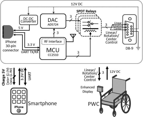
TDS–iPhone–PWC interface block diagram.
Since Enhanced Display provides access to a 12 V supply, which is backed by the large PWC batteries, a dc–dc converter was added to the TDS–iPhone–PWC interface to charge the iPhone via a 5 V supply while the TDS is being used. Moreover, three relays are driven by the CC2510, which normally connect the center, linear, and rotation lines to the DAC. However, if the iPhone is accidentally detached from the interface or the microcontroller supply line is interrupted for any reason, the relays automatically switch these lines to a set of default values, which immediately stop the PWC and show an error message on the Enhanced Display. Table I summarizes the key specifications of the TDS–iPhone–PWC hardware.
TABLE I.
TDS–iPhone–PWC Hardware Specifications
| Parameter | Value |
|---|---|
| Control Unit | |
| Microcontroller | CC2510, Texas Instruments |
| Sampling Rate | 50 Hz |
| RF Frequency/Data Rate | 2.4 GHz/500 kbps |
| Operating Voltage /Current | 2.5 V/6.5 mA |
| Power Source (Batteries) | 2×AAA, 1700 mAh |
| Magnetic Sensor Module | |
| Type | HMC1043, Magnetoresistive, Honeywell |
| Resolution | 0.012 uT |
| Magnetic Tongue Stud | |
| Magnetic Tracer Size | ∅4.8 mm × 1.5 mm |
| Gauge and Length of Barbell | 12 gauges and 12/15/17/21 mm |
| Top Ball Size | ∅8 mm × 3.5 mm |
| Surface Magnetic Strength (Br) | 3000 Gauss |
| TDS-iPhone PWC Interface | |
| Microcontroller | CC2510, Texas Instruments |
| RF Frequency/Data Rate | 2.4 GHz/500 kbps |
| State Vector Updates | AD5724, Analog Device |
| Connectors | Standard iPhone 30 pin and DB-9 pin |
| PC-iPhone Data Transfer Cable | |
| USB to serial UART interface | FTDI Chip-FT232RQ |
| Connectors | Standard iPhone 30 pin and USB |
| iPhone/iPod Touch | |
| CPU Core | 620 MHz Arm 1176JZ(F)-S |
| Memory | 128 MB DRAM |
| Operating System | iOS 3.1.2 |
| Display | 480 × 320 pixels |
C. TDS–iPhone–PWC Software
-
1)
EMI Suppression: To reduce the effects of EMI, a stereo-differential cancellation algorithm has been employed, which subtracts the measurements made by each pair of 3-axial magnetic sensors after mathematically rotating one of them to be in parallel with the other [19]. This subtraction suppresses the undesired common mode signals between the two modules, which are mostly due to the EMI, while magnifying the differential mode components, which are mainly generated by the magnetic tracer on the tongue. The EMF suppression algorithm can be applied to any pair of sensor modules on the TDS headset to obtain a set of differential sensor outputs. For instance, we used the differential sensor outputs of the <front-left and front-right> pair to detect the TDS commands. On the other hand, differential outputs from the <front-left and back-left> and <front-right and back-right> pairs were used to generate the proportional state vector that was needed to control the PWC rotation in the semiproportional control strategy (see Section II-C3).
-
2)
Sensor Signal Processing: Following EMI suppression, the SSP algorithm detects up to six user-defined tongue commands (plus neutral) from differential magnetic sensor outputs. For controlling a PWC, only five TDS commands were needed: forward, backward, left, right, and neutral. Following on-screen cues, shown in Fig. 5(a), subjects initially trained the system by repeatedly and consistently placing their tongues at four suggested command positions plus the tongue resting position, which was considered as the neutral command. Training data were fed into a feature extraction algorithm, which used principle component analysis (PCA) to form a set of clusters in a virtual 3-D space, shown in Fig. 5(b). Each cluster represents one of the five TDS commands. During normal operation, any incoming data point is first reflected onto the PCA space and then classified using eight different classifiers, including K-nearest neighbors (KNN) based on Mahalanobis and Euclidean distances, linear, and quadratic. Each classifier generated its results independently, and the majority voting mechanism was used to decide on the final command with a high level of accuracy and robustness [29].
-
3)
TDS–PWC Control Strategies: The standard controller for PWCs is a joystick, which is a proportional hand-operated controller. The current TDS, on the other hand, is a switch-based tongue-operated alternative. Therefore, it is imperative to find the most intuitive and effective way for novice TDS users to conduct this important task [20]. We have adopted three strategies for PWC control in this study: 1) unlatched; 2) latched; and 3) semiproportional, each of which updates the linear and rotation state vectors that control the PWC motion in a different way.
Unlatched and latched strategies utilize four TDS commands for forward, backward, left, and right motions. In the unlatched mode, users need to hold their tongue at each command position to keep the PWC moving in that direction at a constant speed. When the neutral command is issued by returning the tongue back to its resting position, the linear and rotational vectors return back to zero at a certain rate until the PWC stops. When the “left” or “right” commands are issued following the “forward” or “backward” commands, the PWC maintains its current linear vector status, while turning according to the rotational vector updates. In the latched strategy, there are five adjustable linear speed levels: backward (−0.95 km/h), stop (0 km/h), forward-1 (0.95 km/h), forward-2 (1.25 km/h), and forward-3 (1.6 km/h). Issuing the forward or backward commands can increase or decrease the linear speed from one level to another, where it latches and allows users to return their tongue back to the resting position or steer the PWC to the left or the right without stopping it.
In the semiproportional strategy, instead of using the classification algorithm to detect user commands, the vector sum of the left-side and right-side differential sensor pair outputs is used. In the calibration stage, users slide their tongue (and the magnetic tracer) over their lips from one corner to the other to determine the extent of the vector sum variations. Quickly touching the left and right cheeks with the tip of the tongue sets the thresholds for detecting the forward or backward commands, respectively. During normal operation, as the users slide their tongues over their lips, the normalized amplitude and polarity of the vector sum directly determines the value of the rotational vector and steer the PWC to the left or right. The linear speed of the PWC, however, is controlled similar to the latched strategy by stepping the speed up or down, one level at a time, as the users quickly touch their cheeks with the tip of the tongue. Table II summarizes how the linear and rotation state vectors are updated with each incoming TDS command in each of the three aforementioned TDS–PWC control strategies.
-
4)
iPhone Applications: Five iPhone apps were developed for this study, which GUIs are shown in Fig. 6. The calibration (including EMI cancellation) and training procedures, described in Sections II-C1 and II-C2, respectively, were implemented in the LabVIEW environment and conducted on a laptop PC to provide the user and researcher with better visual feedback. The researcher specified the testing location, subject ID number, and session number using the Folder selection app, shown in Fig. 6(b), which created a folder to store all the training and testing data of that specific subject/session. Once the researcher ran the Data Transfer app, shown in Fig. 6(c), the calibration/training package was transferred from the PC to iPhone either wirelessly, as shown in Fig. 1, or via the data transfer cable, shown in Fig. 2(g).
Fig. 5.
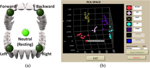
(a) Recommended TDS command positions in the mouth for four directional commands and the tongue resting position as the neutral command. (b) A sample set of training results displayed in the 3-D virtual PCA space.
TABLE II.
State Vector Updates in Three TDS–PWC Control Strategies
| Command | Unlatched | Latched | Semi-Proportional |
|---|---|---|---|
| Resting | *Lin ➔ `0' | Lin ➔ No change | Lin ➔ No change |
| **Rot ➔ `0' | Rot ➔ `0' | Rot ➔ `0' | |
|
| |||
| Forward | Lin ➔ 1.6km/h | Lin ➔ 1-level up | Lin ➔ 1-level up |
| Rot ➔ `0' | Rot ➔ No change | Rot ➔ No change | |
|
| |||
| Backward | Lin ➔ −0.95km/h | Lin ➔ 1-level down | Lin ➔ 1-level down |
| Rot ➔ `0' | Rot ➔ No change | Rot ➔ No change | |
|
| |||
| Left | Lin ➔ `0' | Lin ➔ No change | Lin ➔ No change |
| Rot ➔ Max | Rot ➔ Max | Rot ➔ Vector sum | |
|
| |||
| Right | Lin ➔ `0' | Lin ➔ No change | Lin ➔ No change |
| Rot ➔ -Max | Rot ➔ -Max | Rot ➔ Vector sum | |
Lin: Linear vector update.
Rot: Rotational vector update.
Fig. 6.
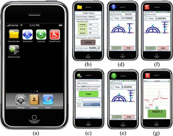
iPhone apps created for the TDS–iPhone–PWC interface platform and its evaluation: (a) main TDS screen, (b) folder selection to enter the location and subject information, (c) training and calibration data transfer from PC to iPhone, (d) unlatched mode screen, (e) latched mode screen, (f) semi proportional mode screen, and (g) recalibration and retraining screen for the semiproportional mode.
Three different TDS–PWC control strategies, described in Section II-C3, each had its own app and GUI as shown in Fig. 6(d)–(f). Each GUI displays the elapsed time, the issued TDS commands, and the status of the linear and rotational vectors among other useful information, such as the TDS headset wireless connectivity and battery status. The overall flowchart of these applications, which run on the iPhone during PWC navigation, is shown in Fig. 7. The app reads the stored calibration/training data package from the iPhone memory and uses it either to classify the incoming raw data frames from the UART and indicate the TDS command or to calculate the vector sum of the differential sensor outputs, depending on the selected control strategy. The results are passed through a command filter, which is a five-sample low-pass moving window that eliminates spurious command selections that may happen due to noise, interference, and unintended tongue motions. Finally, it updates the linear and rotation vectors and sends them via UART to the CC2510 in the TDS–iPhone–PWC interface (see Fig. 4). We have also developed iPhone apps for recalibration and retraining, as shown in Fig. 6(g), in case they were needed during the trial.
Fig. 7.
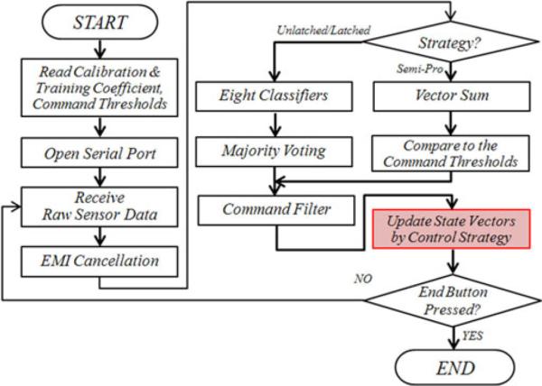
Flowchart of the TDS–iPhone–PWC interface applications running on the iPhone.
III. Performance Evaluation
A. Human Subjects
Twenty-four able-bodied human subjects were recruited from the Atlanta (14 subjects) and Chicago (10 subjects) metropolitan areas, nine of whom completed the entire trial. Most dropouts occurred during the initial phase of the trial, suggesting that some of the recruited subjects might have only been interested in receiving a free tongue piercing. Of the Atlanta subjects, five dropped out expressing dissatisfaction with the location or appearance of the tongue piercing, two reported that the tongue barbell fell out and the piercing closed up, and two were lost to follow-up. Of the Chicago subjects, three were excluded during screening related to the presence of ankyloglossia (anteriorly based frenulum or tongue tie) leading to restricted tongue motion [30], one dropped out due to pain after tongue piercing, and two dropped out during the TDS testing sessions, one related to medical issues unrelated to the study and one related to the time commitment. The group that completed the trial consisted of four male and five female subjects aged 19–29 years old. Five of them (four males and one female) participated at Georgia Institute of Technology (GT), Atlanta, GA and the rest of them (four females) were at Northwestern University (NU), Chicago, IL. The trial was approved by the institutional review boards (IRB) at both sites, and an informed consent form was obtained from each subject prior to the experiment. All subjects were new to the TDS and PWC but were quite familiar with the use of computers and smartphones.
B. Experimental Procedure
-
1)
Tongue Piercing: Tongue piercing was conducted in out-patient medical facilities under medical supervision of a physician at each site. Details of the procedure have been described elsewhere [31], [32]. Related to the known swelling that occurs following tongue piercing, it is standard to insert a long barbell at first and to replace it with a shorter barbell after 4 weeks when the tongue has returned to its original size. For this study, the initial tongue barbell was a standard stainless steel internally threaded barbell with regular threaded balls at each end. Subjects were followed by phone at 24- and 48-h postpiercing and then were seen again at 72 h by the physician to ensure all was well. During this early period, photographs of the tongue were taken and tongue size and volume were measured before and after piercing on a daily basis using a Boley gauge and oral plethysmography, respectively. In the latter method, subjects were asked to fill their mouth with as much water as they could comfortably hold without swallowing, and pour it into a beaker for volumetric measurement. This measurement was repeated five times and averaged to reduce variability.
-
2)
Tongue Barbell Exchange: Further phone contacts were made weekly until week 4, at the end of which the standard initial tongue barbell was removed and a shorter titanium magnet containing barbell was inserted (see Section II-A and Fig. 1). The appropriate length of the barbell was determined based on the measured thickness of the tongue. After the exchange, subjects were scheduled to test the TDS for five consecutive trial sessions with the trial interval ranging from 2 to 10 days. Each PWC trial lasted ~1.5 h on average. During the same session, subjects were also tested on the use of TDS for computer access [21], [33].
-
3)
Calibration: Subjects wore the TDS headset and the researcher adjusted the sensor poles to be symmetrical near the subjects' lip corners, as shown in Fig. 8(a). Using a 22″ LCD monitor, a laptop PC, and a dedicated GUI that guided the researcher step-by-step, subjects started to move their heads in all directions for ~30 s, while keeping their tongue stationary so that the EMI suppression algorithm, described in Section II-C1, could collect samples from the environment.
-
4)
Training the TDS and Navigation Practice: Recommended command positions, shown in Fig. 5(a), were randomly highlighted on the PC screen by turning the green lights on and playing an auditory cue. Subjects held their tongues stationary at each command position for ~1 s while a beep was played. Each command was repeated ten times for a total of 50 samples in the PCA space. At the end of the training session, the GUI generated a 3-D view of the command clusters in the PCA space, which is shown in Fig. 5(b), and the researcher was given the opportunity to eliminate the outliers. To evaluate the quality of training, a short on-screen maze navigation task was conducted to simulate the PWC driving via TDS.
-
5)
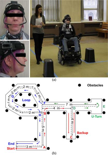
PWC Navigation: Fig. 8(a) shows a typical experimental setting with a subject wearing the TDS headset and the researcher walking next to the PWC with an emergency stop switch. Subjects drove the PWC using tongue motion through an ~50 m obstacle course with 13 turns and 24 obstacles, which floor plan is shown in Fig. 8(b). During the first session, subjects were asked to drive the PWC using unlatched, latched, and semiproportional strategies in this order (see Section II-C3). We had found in [20] that the unlatched mode is the most suitable for a novice TDS user. In the next four sessions, the order of the driving strategies was randomized to minimize the learning bias. Each strategy was repeated four times, one for practice and three for testing, during which the researcher recorded the completion time and the number of navigation errors, including collisions with obstacles, PWC wheels moving out of the track, and emergency stops. Each round included a simulated emergency stop when an alarm was sounded on the iPhone at a random time. The subjects had already been instructed to hit the emergency stop button on the headrest [see Fig. 2(b)] to shut down and stop the PWC immediately. Subjects then hit the same button again to turn the PWC on and continue the rest of the trial.
-
6)
Questionnaire: At the end of each session, subjects responded to 15 questions in the five-point Likert scale to subjectively evaluate their TDS experience. Six of these questions were related to the TDS–PWC driving, which are summarized in the following section.
Fig. 8.
(a) Subject wearing the TDS headset and driving the Q6000 PWC, while receiving visual feedback on the TDS–iPhone–PWC interface mounted on the left armrest. (b) Floor plan of the ~50 m obstacle course including the driving trajectory.
IV. Results
A. Tongue Piercing
For temporary usage of the TDS, the magnetic tracer can be attached to the tongue using tissue adhesives, such as PeriAcryl (GluStitch, Canada), which is commonly used in dentistry [23]. However, after 1 or 2 h the tracer loosens and may fall off, imposing the risk of aspiration or swallowing of the magnet. Therefore, tissue adhesives are not suitable for long-term usage of the TDS. Tongue piercing, on the other hand, is commonly practiced outside medical profession, i.e., without requiring surgery or hospitalization, and it is currently the safest and most feasible method that we have been able to find for long-term attachment of the magnetic tracer to the TDS users' tongues. A key advantage of the tongue piercing is that it is reversible and can be easily removed with minor side effects. Moreover, we intended to develop a medically appropriate procedure for tongue piercing for medical purposes, which had not been documented in the medical literature before [31].
Fig. 9 shows the front and side views of a subject's tongue before and after piercing. The tongue normally starts swelling immediately after piercing and reaches its maximum volume about 24 h postpiercing. This has been confirmed with our oral plethysmography results, shown in Fig. 10, which indicate that the volume of the water held in the subjects' mouth reached its minimum in day-1 postpiercing. However, the tongue swelling begins to subside following that point as the tongue gradually recovers and reaches its original size well before week 4, when the barbell was exchanged. The average residual oral volume of the male subjects (92.9 ± 10.8 mL) was 12.7% larger than the female subjects (81.1 ± 15.5 mL), which is consistent with the larger average size of the tongue and oral cavity in males compared to females [34].
Fig. 9.
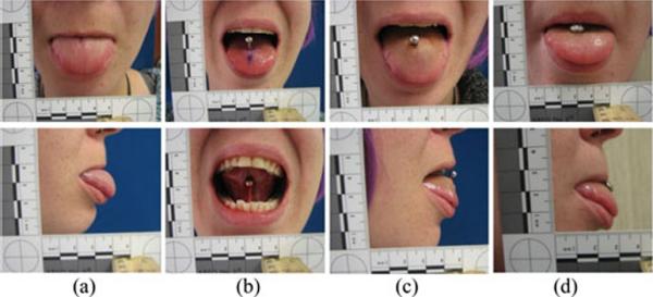
(a) Front and side views of a subject's tongue before piercing, (b) right after tongue piercing with the standard stainless steel barbell, (c) day-3 postpiercing with some tongue swelling, and (d) following exchange in week 4 with the magnetic tongue barbell made of titanium.
Fig. 10.
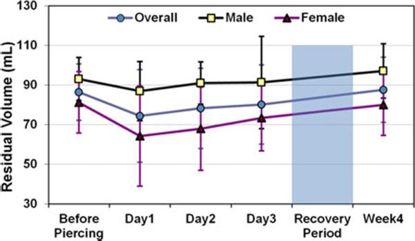
Volumetric measurement of nine subjects' (four males and five females) oral cavities over 4 weeks using the oral plethysmography method to study the tongue swelling.
Location of the piercing on the tongue is important because on one hand bringing the magnetic tracer closer the tip of the tongue gives it a wider range of motion within the oral cavity, and makes it easier for the SSP algorithm to discriminate between adjacent TDS command locations. On the other hand, if the tongue stud is too large or too close to the tip of the tongue, the risk of damage to the teeth and gum increases [32]. Therefore, the optimal position of the tongue piercing should be determined by the medical personnel based on the TDS users' size of the tongue and oral anatomy. In our trial, the average separation between the tip of the tongue and the piercing site in GT and NU subjects was measured 24 ± 3.6 and 21.8 ± 0.43 mm, respectively.
B. Completion Time, Navigation Error, and Emergency Stops
During five sessions, the average completion time decreased from 250 s in the first session to less than 170 s in the fifth session, as shown in Fig. 11(a). The improvement was faster from the first to the second session (>20%); however, it continued to the last session at an average rate of ~9% per session.
Fig. 11.

TDS–PWC measurement results over five sessions in 5 weeks: (a) completion time; (b) number of navigation errors (collisions, and out of track researcher-issued emergency stops); (c) number of researcher-issued emergency stops per session.
Previous experiments on the use of tongue-operated devices for driving wheelchairs in [23] and [14] have reported an average speed of 12 and 20 m/min, respectively. A direct comparison might be difficult because the floor plan of the obstacle course in the current experiment in Fig. 8(b) was slightly different and the test included a simulated emergency stop, which added to the overall completion time. Nonetheless, the average speeds of 12.25 and 17.77 m/min in the first and fifth sessions, respectively, were well within the previously reported rates. Moreover, according to Fig. 11(b) the number of navigation errors, including collisions, out of tracks, and researcher initiated emergency stops gradually dropped from ~8/session in unlatched and latched modes to only ~2/session. For the semiproportional mode, the error rate was generally lower, dropping from ~3/session to ~2/session. Due to the position of tongue piercing and the shape of the tongue, one of the subjects was unable to operate the PWC with the semiproportional strategy. Hence, the results for this mode are averaged among eight subjects. If the PWC was completely out of track or too close to a hard object, like a wall, emergency stop was issued by the researcher without stopping the timer. Fig. 11(c) shows that the need for researcher-initiated emergency stops was also reduced over the course of five sessions, and in the case of semiproportional strategy, almost no emergency stops were needed during the last two sessions.
C. Questionnaire
Fig. 12 depicts a summary of six TDS–PWC driving experience questions that were asked at the end of each session. Perceived mental effort to remember the TDS tongue positions was gradually shifted from medium to a low level. Similarly, subjects found that driving the PWC through the obstacle course accurately via TDS became easier over five sessions. The most consistent subjective result was that as subjects gained more experience with the TDS–iPhone–PWC interface, a strong majority of them (eight out of nine) found that the speed of PWC was too slow. This indicates a steady improvement in their confidence and skills in managing the driving task. Only one subject reported tongue fatigue at the end of the fifth session. Four out of nine subjects reported some jaw fatigue after the first session. Four subjects continued to experience jaw fatigue over the course of the trial but this jaw fatigue became less by the end of five sessions.
Fig. 12.
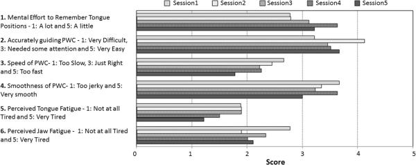
Summary of the results for six questions related to the TDS–PWC navigation, which were asked from subjects at the end of each session.
D. Statistical Analysis
To assess further the learning effects in using the TDS for PWC navigation, a linear mixed model for repeated measurements was used in our statistical analysis utilizing the Statistical Package for the Social Sciences (SPSS). SPSS is capable of handling correlated data containing both fixed and random effects with unequal variances and missing data points [35]. Completion time in Fig. 11(a) shows that the learning effect from the first to second session was significantly higher than learning between any other two successive sessions (p = 0.029). Testing center (GT versus NU) did not have a significant effect (p = 0.350), and there was no significant difference between the three different control strategies (p = 0.598).
Navigation error lessened significantly from the first to the last session for the unlatched and latched strategies (p = 0.001).
However, that was not the case for the semiproportional strategy (p = 0.746), which had a low number of errors from the beginning. The effect was similar at both testing centers (p = 0.839). The number of emergency stops was affected by the center and session combination (p = 0.046), and there were different patterns of improvement for the two centers over five sessions. On average at GT, emergency stop was activated 0.083 times/session by the researcher. At NU, this number was 0.328 times/session. This might be because of the different environments in which the trials were conducted. At GT, the TDS–PWC navigation experiment was conducted on a spacious outdoor parking deck, while at NU it was done in a large indoor space with only ~1 m clearance from the walls and columns in certain locations. As a result, the researchers at NU were more likely to press the emergency stop button in order to avoid an accident when subjects drove the PWC outside tracks.
It should be noted that the GT site researchers (electrical engineers) were generally more familiar with the TDS than those at the NU site (clinicians). We do not have the means to assess independently the effect of researchers and their backgrounds on the outcomes.
V. CONCLUSION
We have developed a TDS–iPhone–PWC interface as part of a wireless and wearable AT to allow individuals with severe disabilities drive PWCs using a headset and a magnetic tongue barbell, while receiving visual feedback on their smartphones. System performance and subject learning were evaluated by nine inexperienced able-bodied subjects in two centers, who drove a PWC in an obstacle course in five sessions over 5 weeks. A significant performance improvement was observed in the second session. This improvement continued over the next three sessions but at a slower pace. Subjects improved their TDS–PWC driving skills over five sessions to the level that they desired increased PWC speed, which was limited to 1.6 km/h for safety reasons. Taking advantage of the powerful smartphone technology, we are going to add other applications to the TDS–iPhone–PWC interface, such as phone dialing, text messaging, email access, and weight management on the PWC. It is also possible to provide the TDS user with auditory or even tactile feedback via its wireless headset. We are currently in the process of evaluating the TDS performance clinically by individuals with severe paralysis (quadriplegia).
ACKNOWLEDGMENT
The authors would like to thank Dr. A. Simon and J. Norman, who performed the tongue piercing and follow-up visits in Atlanta. Pride Mobility Products Corp (Exeter, PA). donated a pair of Q6000 wheelchairs in support of this research. Anatometal Inc. (Santa Cruz, CA) designed and manufactured the magnetic tongue barbells. They would also like to thank participants in the trial and members of the GT-Bionics Laboratory.
This work was supported in part by the National Institute of Biomedical Imaging and Bioengineering under Grant 1RC1EB010915 and in part by the National Science Foundation under Award CBET-0828882 and Award IIS-0803184.
Biographies
 Jeonghee Kim (S'11) was born in 1983. She received the B.S. degrees in electrical engineering from the Kyungpook National University, Sangju, Gyeongbuk, Korea, and from the University of Texas at Dallas, Richardson, in 2007 and 2008, respectively, and the M.S. degree in electrical engineering and computer science from the University of Michigan, Ann Arbor, in 2009. She is currently working toward the Ph.D. degree at the GT-Bionics Laboratory, Georgia Institute of Technology, Atlanta.
Her research interests include system design for biomedical devices with embedded mobile application, human computer interaction, and assistive technologies.
 Xueliang Huo (S'07) was born in 1981. He received the B.S. and M.S. degrees in mechanical engineering (instrument science and technology) from Tsinghua University, Beijing, China, in 2002 and 2005, respectively, and the Ph.D. degree in electrical and computer engineering from the Georgia Institute of Technology, Atlanta, in 2011. His Ph.D. research was on developing wearable and wireless assistive technologies as well as human computer interfaces for people with severe disabilities.
He is currently a Hardware Engineer at Microsoft Corporation, Redmond, WA.
 Julia Minocha received the B.S. degree in biochemistry from the University of Notre Dame, Notre Dame, IN, and the Medical School degree from the Feinberg School of Medicine, Northwestern University, Chicago, IL.
She completed an internal medicine residency at Northwestern University and was a member of the internal medicine clinical faculty for one year. She then joined the Department of Dermatology, Feinberg School of Medicine, and completed a medical dermatology fellowship with the support of the National Psoriasis Foundation and is now pursuing her dermatology residency training.
 Jaimee Holbrook received the B.A. degree in biology from the University of Chicago, IL, and the Medical degree from the Feinberg School of Medicine, Chicago, IL.
She is currently a Clinical Research Fellow (second year) in the Department of Dermatology, Feinberg School of Medicine, Northwestern University.
 Anne Laumann was born in England. She graduated MBChB from the University of Birmingham, England in 1968. She pursued post-graduate training in general internal medicine in the United Kingdom receiving MRCP(UK) in 1972.
She was a dermatology research fellow at Scripps Clinic and Research Foundation, CA, and a resident in Dermatology at the University of Chicago. Prior to joining the dermatology faculty at Northwestern University, she held academic positions at both the University of Illinois, Chicago, and the University of Chicago, and directed the dermatology unit at Michael Reese Hospital. She is a fellow of the American Academy of Dermatology and an active member of the Chicago Dermatological Society, the Illinois Dermatological Society, the Women's Dermatologic Society, the Medical Dermatology Society, the Association of Professors of Dermatology, the Society of Investigative Dermatology and the British Association of Dermatology. She has been Vice President of the Chicago Dermatological Society and President of the Illinois Dermatological Society. She is currently on the board of the Medical Dermatology Society and is President of the Medical Faculty Council of the Feinberg School of Medicine. She is a Fellow of the Institute of Medicine of Chicago. She is a Professor of Dermatology, Director of the Collagen Vascular Disorders Clinic, and Section Chief of General Dermatology at the Feinberg School of Medicine, Northwestern University, Chicago.
 Maysam Ghovanloo (S'00–M'04–SM'10) was born in 1973 in Tehran, Iran. He received the B.S. degree in electrical engineering from the University of Tehran, Tehran, in 1994, the M.S. degree in biomedical engineering from the Amirkabir University of Technology, Tehran, in 1997, and the M.S. and Ph.D. degrees in electrical engineering from the University of Michigan, Ann Arbor, in 2003 and 2004, respectively.
From 2004 to 2007, he was an Assistant Professor in the Department of Electrical and Computer Engineering, North Carolina (NC) State University, Raleigh. In June 2007, he joined the faculty of Georgia Institute of Technology, Atlanta, where he is currently an Assistant Professor and Founding Director of the GT-Bionics Laboratory, School of Electrical and Computer Engineering. He has authored or coauthored more than 100 peer-reviewed conference and journal publications.
Dr. Ghovanloo is an Associate Editor of the IEEE Transactions on Biomedical Engineering and the IEEE Transactions on Biomedical Circuits and Systems, and a member of the Imagers, MEMS, Medical, and Displays (IMMD) subcommittee at the International Solid-State Circuits Conference (ISSCC). He is the 2010 recipient of a CAREER award from the National Science Foundation. He has also received awards in the 40th and 41st Design Automation Conference (DAC)/ISSCC Student Design Contest in 2003 and 2004, respectively. He has organized several special sessions and was a member of Technical Review Committees for major conferences in the areas of circuits, systems, sensors, and biomedical engineering. He is a member of the Tau Beta Pi, AAAS, Sigma Xi, and the IEEE Solid-State Circuits Society, IEEE Circuits and Systems Society, and IEEE Engineering in Medicine and Biology Society.
REFERENCES
- [1].AbleData. 2012 Apr; [Online] Available: http://www.abledata.com/
- [2].Cook AM, Hussey SM. Assistive Technologies: Principles and Practice. 3rd ed Mosby; NY: 2007. [Google Scholar]
- [3].Origin Instruments Corporation Sip and Puff Switch. 2009 May 6; [Online] Available: http://orin.com/access/sip_puff/sp_mu/index.htm.
- [4].Barea R, Boquete L, Mazo M, Lopez E. System for assisted mobility using eye movements based on electrooculography. IEEE Trans. Rehabil. Eng. 2002 Dec;10(no. 4):209–218. doi: 10.1109/TNSRE.2002.806829. [DOI] [PubMed] [Google Scholar]
- [5].Chen YL, Tang FT, Chang WH, Wong MK, Shih YY, Kuo TS. The new design of an infrared-controlled human computer interface for the disabled. IEEE Trans. Rehabil. Eng. 1999 Dec;7(no. 4):474–481. doi: 10.1109/86.808951. [DOI] [PubMed] [Google Scholar]
- [6].Chin CA, Barreto A, Cremades JG, Adjouadi M. Integrated electromyogram and eye-gaze tracking cursor control system for computer users with motor disabilities. J. Rehab. Res. Develop. 2008;45:161–174. doi: 10.1682/jrrd.2007.03.0050. [DOI] [PubMed] [Google Scholar]
- [7].San Agustin J, Skovsgaard H, Mollenbach E, Barret M, Tall M, Hansen DW, Hansen JP. Evaluation of a low-cost open-source gaze tracker. Proc. 2010 Symp. Eye-Tracking Res. Appl. 2010 Mar.:77–80. [Google Scholar]
- [8].Agustin, Tall M, Alapetite A, San J, Skovsgaard HH, Hansen JP, Hansen DW, Mollenbach E. Gaze-controlled driving. Proc. 27th Int. Conf. Extended Abstract on Human Factors in Computing Systems. 2009 Apr.:4453–4458. [Google Scholar]
- [9].Wolpaw JR, Birbaumer N, McFarland DJ, Pfurtscheller G, Vaughan TM. Brain–computer interfaces for communication and control. Clin. Neurophysiol. 2002;113:767–791. doi: 10.1016/s1388-2457(02)00057-3. [DOI] [PubMed] [Google Scholar]
- [10].Rebsamen B, Guan C, Zhang H, Wang C, Teo C, Ang MH, Burdet E. A brain controlled wheelchair to navigate in familiar environments. IEEE Trans. Neural Syst. Rehabil. Eng. 2010 Dec;18(no. 6):590–598. doi: 10.1109/TNSRE.2010.2049862. [DOI] [PubMed] [Google Scholar]
- [11].Iturrate I, Antelis JM, Kubler A, Minguez J. A noninvasive brain-actuated wheelchair based on a P300 neurophysiological protocol and automated navigation. IEEE Trans. Robot. 2009 Jun;25(no. 3):614–627. [Google Scholar]
- [12].Barreto A, Scargle SD, Adjouadi M. A practical EMG-based human-computer interface for users with motor disabilities. J. Rehab. Res. Develop. 2000 Jan;37:53–64. [PubMed] [Google Scholar]
- [13].Felzer T, Strah B, Nordmann R, Miglietta S. Alternative wheelchair control involving intentional muscle contractions. Int. J. Artif. Intell. Tools. 2009 Jun;18:439–465. [Google Scholar]
- [14].Lund ME, Christiensen HV, Caltenco HA, Lontis ER, Bentsen B, Struijk LNSA. Inductive tongue control of powered wheelchairs. Proc. IEEE 32nd Eng. Med. Biol. Conf. 2010 Sep;:3361–3364. doi: 10.1109/IEMBS.2010.5627923. [DOI] [PubMed] [Google Scholar]
- [15].Caltenco HA, Struijk LNSA, Breidegard B. TongueWise: Tongue–computer interface software for people with tetraplegia. Proc. IEEE 32nd Eng. Med. Biol. Conf. 2010 Sep;:4534–4537. doi: 10.1109/IEMBS.2010.5626033. [DOI] [PubMed] [Google Scholar]
- [16].Christopher and Dana Reeve Foundation. 2012 Apr; [Online] Available: http://www.christopherreeve.org.
- [17].Carlson D, Ehrlich N. Report of U.S. Department of Education. National Institute on Disability and Rehabilitation; Washington, DC: 2005. Assistive technology and information technology use and need by persons with disabilities in the United States. [Google Scholar]
- [18].Spinal Cord Injury: Hope Through Research. National Institute of Neurological Disorders and Stroke (NINDS); NIH: Apr, 2012. [Online] Available: http://www.ninds.nih.gov/disorders/sci/detail_sci.htm. [Google Scholar]
- [19].Huo X, Wang J, Ghovanloo M. A magneto-inductive sensor based wireless tongue-computer interface. IEEE Trans. Neural Syst. Rehabil. Eng. 2008 Oct;16(no. 5):497–504. doi: 10.1109/TNSRE.2008.2003375. [DOI] [PMC free article] [PubMed] [Google Scholar]
- [20].Huo X, Ghovanloo M. Using unconstrained tongue motion as an alternative control surface for wheeled mobility. IEEE Trans. Biomed. Eng. 2009 Jun;56(no. 6):1719–1726. doi: 10.1109/TBME.2009.2018632. [DOI] [PMC free article] [PubMed] [Google Scholar]
- [21].Yousefi B, Huo X, Veledar E, Ghovanloo M. Quantitative and comparative assessment of learning in a tongue-operated computer input device. IEEE Trans. Info. Tech. Biomed. 2011 Sep;15(no. 5):747–757. doi: 10.1109/TITB.2011.2158608. [DOI] [PMC free article] [PubMed] [Google Scholar]
- [22].Yousefi B, Huo X, Kim J, Veledar E, Ghovanloo M. Quantitative and comparative assessment of learning in a tongue-operated computer input device: Part II. Navigation tasks. IEEE Trans. Info. Tech. Biomed. doi: 10.1109/TITB.2012.2191793. [DOI] [PMC free article] [PubMed] [Google Scholar]
- [23].Huo X, Ghovanloo M. Evaluation of a wireless wearable tongue–computer interface by individuals with high-level spinal cord injuries. J. Neural Eng. 2010 Apr;7(no. 2):1–12. doi: 10.1088/1741-2560/7/2/026008. [DOI] [PMC free article] [PubMed] [Google Scholar]
- [24].Oresko JJ, Jin Z, Cheng J, Huang S, Sun Y, Duschl H, Cheng AC. A wearable smartphone-based platform for real-time cardiovascular disease detection via electrocardiogram processing. IEEE Trans. Info Tech. Biomed. 2010 May;14(no. 3):734–740. doi: 10.1109/TITB.2010.2047865. [DOI] [PubMed] [Google Scholar]
- [25].Chung W, Yau C, Shin K, Myllyla R. Proc. IEEE 29th Eng. Med. Biol. Conf. Lyon, France: 2007. A cell phone based health monitoring system with self analysis processor using wireless sensor network technology; pp. 3705–3708. [DOI] [PubMed] [Google Scholar]
- [26].LeMoyne R, Mastroianni T, Cozza M, Coroian C, Grundfest W. Implementation of an iPhone as a wireless accelerometer for quantifying gait characteristics. Proc. IEEE 32nd Eng. Med. Biol. Conf. 2010 Sep;:3847–3851. doi: 10.1109/IEMBS.2010.5627699. [DOI] [PubMed] [Google Scholar]
- [27].Want R. iPhone: Smarter than the average phone. IEEE Pervasive Comput. 2010 Jul-Sep;9(no. 3):6–9. [Google Scholar]
- [28].Kim J, Huo X, Ghovanloo M. Wireless control of smartphones with tongue motion using tongue drive assistive technology. Proc. IEEE 32nd Eng. Med. Biol. Conf. 2010 Sep;:5250–5253. doi: 10.1109/IEMBS.2010.5626294. [DOI] [PMC free article] [PubMed] [Google Scholar]
- [29].Sadeghian EB, Huo X, Ghovanloo M. Command detection and classification in tongue drive assistive technology. Proc. IEEE 33rd Eng. Med. Biol. Conf. 2011 Sep;:5465–5468. doi: 10.1109/IEMBS.2011.6091394. [DOI] [PMC free article] [PubMed] [Google Scholar]
- [30].Tongue-Tie (Ankyloglossia), Otolaryngology Houston. 2012 Apr; [Online]. Available: http://www.ghorayeb.com/TongueTie.html.
- [31].Minocha JS, Holbrook JS, Ghovanloo M, Laumann AE. Development of a tongue-piercing method for use with assistive neuro-technology. doi: 10.1001/jamadermatol.2013.7165. unpublished. [DOI] [PMC free article] [PubMed] [Google Scholar]
- [32].Holbrook J, Minocha J, Laumann A. Body piercing: Complications and prevention of health risks. Amer. J. Clin. Dermatology. 2012;13(no. 1):1–17. doi: 10.2165/11593220-000000000-00000. [DOI] [PubMed] [Google Scholar]
- [33].Minocha J, Holbrook J, Yousefi B, Kim J, Huo X, Rowles D, Bartlett B, Ruppert L, Johnson-Bice S, West D, Veledar E, Roth E, Ghovanloo M, Laumann A. Use of a magnet-containing barbell in the tongue to operate the tongue drive system. J. Investigat. Dermatol. 2011;131:S80. [Google Scholar]
- [34].Oliver RG, Evans SP. Tongue size, oral cavity size, and speech. Angle Orthod. 1986 Jul;56(no. 3):234–243. doi: 10.1043/0003-3219(1986)056<0234:TSOCSA>2.0.CO;2. [DOI] [PubMed] [Google Scholar]
- [35].Linear Mixed-Effects Modeling in SPSS: An Introduction to the MIXED Procedure. 2012 Apr; [Online] Available: http://www.spss.ch/upload/1126184451_Linear%20Mixed%20Effects%20Modeling%20in%20SPSS.pdf.


