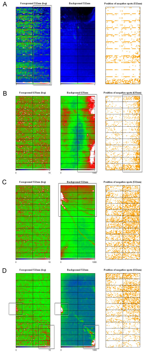
Figure 3.

Spatial report. Output from the spatial analysis method shows various representations of analyzed data according to the location of the spot on the array. A pseudo color representation is used to display log2 transformed foreground intensities and raw backgroundintensities. A plot showing the location of the negative values across the array is also generated. The cutoff value for the background data plot can be set in the GUI prior to analysis. A) Spatial plot from a hybridization showing clear fading at the right part of the slide. B) High background values results in increased frequency of negative spots. C) Inadequate post-hybridization washing often results in distinct background patterns. D) Bleeding of signal from the actual spot into the background area results in regions of high background values that are also visible in the foreground plot.
