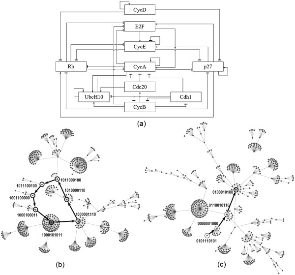
Figure 4.
Mammalian cell cycle network analysis using NeuroDNet. (a) Cell cycle regulatory graph was redrawn from Fauré et al.[53]. Transition of states output of the NeuroDNet using a synchronous simulation has been shown. The cell cycle states through which a mammalian cell undergoes is shown (cyclic attractor) (b). The singleton attractor represents a steady state condition of the cell. The trajectory followed by the cell to reach G0 phase where intermediate nodes in the path depict the synchronous progression (c). The binary sequences shown in (b) and (c) correspond to the state of the nodes (i = 1, 2, …, 10) in the order given in Table 1 .

