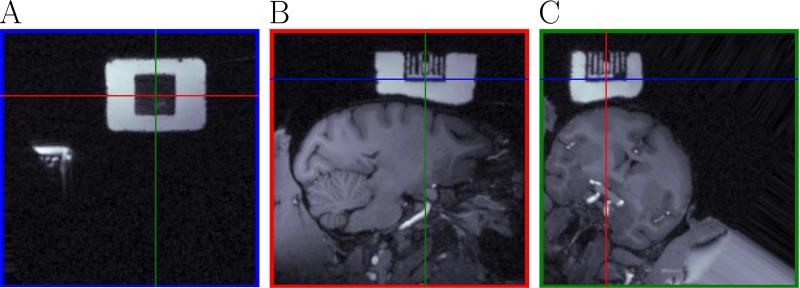
Figure 3.
Definition of the chamber coordinate system. This figure shows the MRI aligned with the chamber coordinate system defined by the user. Panel A represents a cut in the MRI corresponding to the blue lines in panels B and C. Panel B represents a cut in the MRI corresponding to the red lines in panels A and C. Panel C represents a cut in the MRI corresponding to the green lines in panels A and B. The intersection of each pair of lines in each panel represents the origin of the chamber coordinate system. Panel A shows part of the posterior recording chamber (also visible in Panel B of Fig. 4) not used for the experiment in this paper. The white block is the fluid filling the chamber. The square black block (A) is the reference grid. White columns (B, C) are the filled grid holes.

