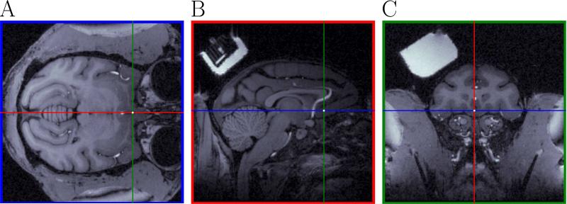
Figure 4.
Prediction of the chamber coordinates to hit a desired neural area from the MRI. This figure shows the targeted neural structure for recordings in the MRI. Same color convention as in Fig. 3. A white dot at the intersection of the pairs of lines in each plot corresponds to the position of the targeted neural area (Panel B shows a posterior recording chamber (partially visible in Panel A of Fig. 3) not used for the experiment in this paper). Panel C shows the recording chamber used for the experiments in the paper.

