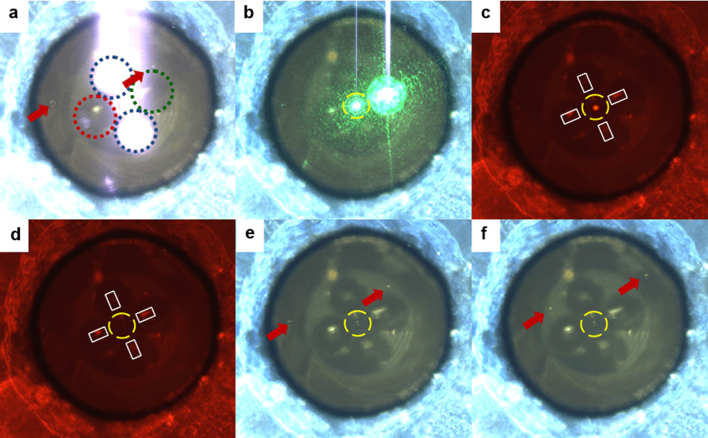
Figure 6. Fluorescence spectroscopy in the microfluidic integrated system.
Sequence of images obtained starting from the frames of Supplementary Video S2. (a) Front-view of the probe: the two fibres indicated by the blue dotted line emit the infrared radiation used to trap the particle. The fibre surrounded by the green circle is connected to the 532-nm laser source, while the one surrounded by the red circle is unused. Red arrows indicate the position of two non-trapped beads. (b) After inserting an IR-filter and switching on the 532-nm laser the green light scattered by the trapped particle (inside the yellow, dashed circle) is evident. (c) A long-pass filter is introduced in the light path to remove the 532-nm radiation from the image and the trapped bead (7.5 μm in diameter) shows an evident red fluorescence. (d) When the 532-nm laser is switched off the fluorescence disappear: the red light visible in the picture is given by coaxial white-light illumination used to illuminate the scene. (e) When the long-pass filter is removed, and the IR-filter is used, it is possible to observe the trapped bead in the centre of the yellow circle, as well as two additional beads indicated by the red arrows. (f) When the flow is restored the trapped bead remains stably trapped, while the other beads flow towards the upper right corner.

