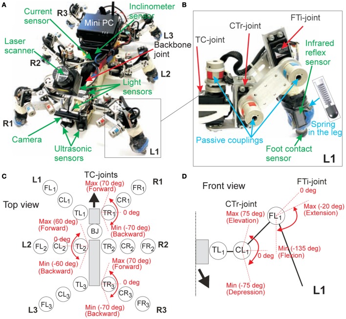
Figure 1.
The biologically-inspired six-legged walking machine AMOS II. (A) AMOS II with its sensors. (B) Examples of components at the left front leg (L1). (C) The location of all motor joints on AMOS II and the maximum and minimum angles of the TC-joints of the right front (R1), left middle (L2), and right hind (R3) legs (top view). The remaining legs on the opposite side have the same ranges; i.e., the range of L1 = R1, the range of R2 = L2, and the range of L3 = R3. (D) The maximum and minimum angles of the CTr- and FTi-joints of L1 (front view). The remaining legs perform the same joint angle ranges. Abbreviations are: TR1, CR1, FR1 = TC-, CTr-, and FTi-joints of the right front leg (R1); TR2, CR2, FR2 = right middle leg (R2); TR3, CR3, FR3 = right hind leg (R3); TL1, CL1, FL1 = left front leg (L1); TL2, CL2, FL2 = left middle leg (L2); TL3, CL3, FL3 = left hind leg (L3); BJ = a backbone joint.

