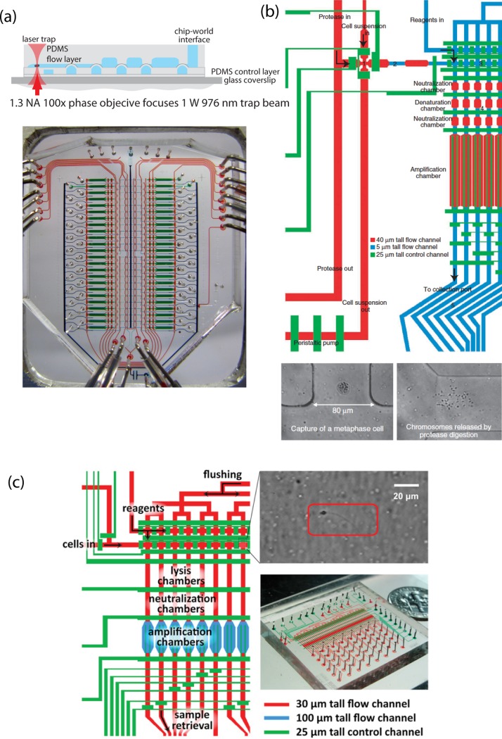
Figure 7.
(a) Diagram of laser trap sorting of single cells. This is a two layer “push-up” device and the laser trap drags the cell past two open valves and then into the lysis chamber. (Below)An optical micrograph of the whole device which was used in Refs. 69, 70, 71, 72. Device was fabricated by the Stanford microfluidic foundry staff. Figure courtesy of P. Blainey. (b) Device schematic for single chromosome sequencing. Red and blue lines represent the flow channels and green are the control. Single cells are trapped in the cross-junction, lysed in the following chamber and then chromosomes are separated into the sequential channels. Optical micrographs (bottom) depict a single metaphase cell in the channel and its chromosomes after lysis.73 Reprinted with permission from H. C. Fan, J. Wang, A. Potanina, and S. R. Quake, Nat. Biotechnol. 29(1), 51–57 (2011). Copyright 2011 Macmillan Publishers Ltd. (c) Device schematic for the single sperm sequencing chip used in Ref. 74. Optical micrograph depicts a single sperm cell trapped a flow channel. Reprinted with permission from J.Wang, H. C. Fan, B. Behr, and S. R. Quake, Cell 150(2), 402–412 (2012). Copyright 2012 Elsevier.

