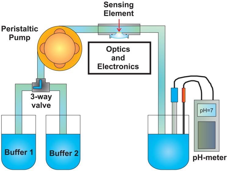
Figure 12.
Schematic representation of the fluidic system used to measure the pH sensor response time. It consists of (i) a closed loop circulator, (ii) the optical head with the sensing element inside, (iii) a beaker with a glass electrode pH-meter to measure the pH of the solution and a thermocouple to measure the temperature of the solution and correct the pH value. A 3-way valve has been added to switch between two different buffer solutions.

