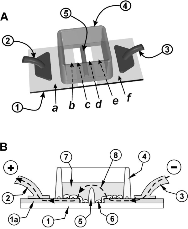
Figure 7.
Electroporation on two co-planar ITO electrodes, formed by removing the ITO coating by chemical etching A: Top view. Cells were grown on an ITO-coated slide from which the coating was removed in a strip as shown. The two conductive sides (a, f), serving as electrodes, were connected to the positive and negative poles of the pulse generator (2) and (3). A nonconductive barrier (5) divides the strip of bare glass in half and separates the chamber into two sections. B: Side view. The slide with the cells growing on the ITO coated and the bare glass regions is shown. When electroporation buffer is added to the chamber to a level above the height of the barrier (5) then an electrical path between the electrodes (e and b) is formed. Note that the ITO layer (1a) is shown with dramatically exaggerated thickness for clarity, although its actual thickness is much less than the thickness of the cells (from [42]).

