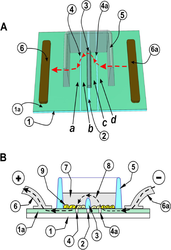
Figure 8.
Electroporation on two co-planar ITO electrodes, formed by removing the ITO coating by etching with Lasers. A: Top view. Cells are grown on a glass slide (1), coated with ITO (1a). The coating is laser-etched in a straight line in the middle (2), essentially forming two electrodes. A dam of Teflon (3) is used to divert the current upwards, thus creating a sharp transition in electric field intensity. A plastic chamber is bonded onto the slide, to form a container for the cells and LY (5). To provide areas where the cells are not electroporated, the ITO was also removed in two parallel lines [(4), (4a)]. Current from a pulse generator flows inwards from each contact point (6 and 6a) to area (d) then over the barrier [(3), arrowheads] to the other side, electroporating cells in area (a). For clarity, the front part of the chamber is removed. B: Side view. The slide (1) with the cells growing on the ITO coated [(1a), light green] and etched, bare glass regions is shown. When electroporation medium (7) is added to the chamber to a level above the height of the dam (3) then an electrical path (arrowheads) between the electrodes (6) and (6a) and the cells (9) growing in this area is formed. Note that the size of the cells and the ITO layer (1a) are shown exaggerated for clarity although the actual thickness of the ITO (800 Å) is much lower than the thickness of the cells.

