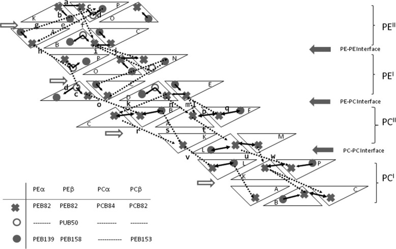
Figure 5.

Representation of one-third of the antenna. Each subunit is represented as a triangle. The names of the subunits are indicated with letters: A, C, E, K, M, and O for α subunits and B, D, F, L, N, and P for β subunits. The solid arrows represent intratrimer paths. The intertrimer paths are represented by discontinuous arrows. An identification letter was added to the paths that are drawn in the figure and correlate them with the transfer rates indicated on Table III.
