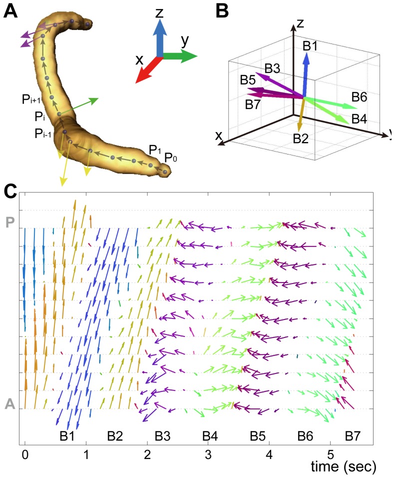
Figure 5. Bending vector analysis of worm motion.
(A) Schematic of the bending vector in a 3-D skeleton. The arrows indicate the bending vector at a skeletal point, Pi. (B) Variable bending vectors of a second skeletal point from the head of a representative worm during crawling. (C) The X-Y projections of bending vectors along the whole body for 5.5 s of crawling. The colors of arrows represent the directions of the bending vectors by linearly converting the components of normalized bending vectors (−1.0∼1.0) to 8-bit colors (0∼255): the X-component is displayed in red (R), the Y-component in green (G), and the Z-component in blue (B).

