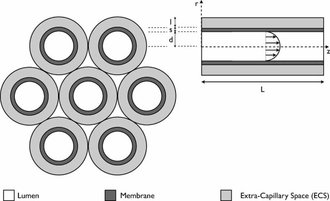
Figure 1.

A schematic of the HFB setup. The left-hand schematic shows the structure of a fiber bundle, comprising seven Krogh cylinder units. The right-hand schematic shows a cross-section through an individual fiber, including the fluid velocity profile in the lumen.
