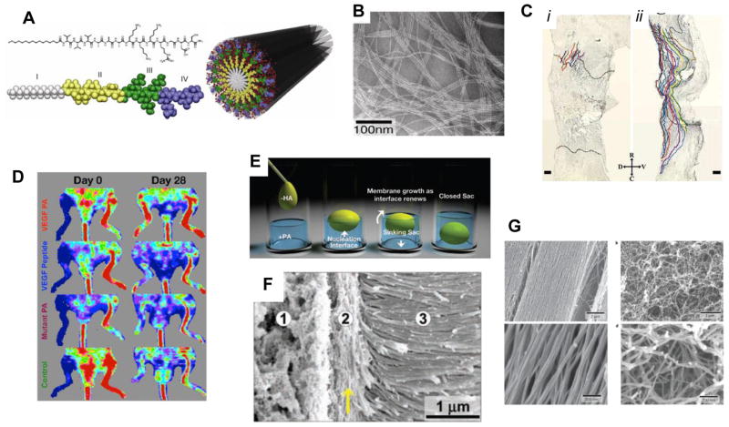
Figure 4. Peptide amphiphiles and their applications.
(A) Chemical structure of a representative peptide amphiphile (PA), and its assembly into nanofibers, with the four primary regions highlighted. Region I: unbranched alkyl (usually C16) tail; region II: a β-sheet forming segment to promote H-bonding along the fiber axis; region III: charged amino acids for solubility; region IV: a peptide epitope to imbue the material with biological signaling. (B) TEM image demonstrating the self-assembly of PAs into high aspect ratio nanofibers, often several microns in length. (C) Injection of a PA solution containing the IKVAV epitope into the damaged spinal cord of a mouse resulted in regeneration of both ascending and descending axons (ii), whereas a control saline injection did not (i). (D) A VEGF-mimetic PA was able to stimulate angiogenesis in a mouse hind-limb ischemia model, restoring more blood flow to the injured limb after 28 days (top image) compared with the peptide alone, or a PA with a non-bioactive sequence. (E) Schematic of self-assembled sac formation upon injection of a polyelectrolyte solution into an oppositely charged PA solution. (F) SEM demonstrating the hierarchical structure of the sac membrane, including the dense arrangement of fibers perpendicular to the membrane (region 3). (G) SEM images of a PA-based monodomain gel, with fibers aligned in the direction of shear (left); a PA solution that was not heat-annealed shows randomly oriented fibers (right). [(A, B): ref. 79; (C): ref. 64; (D): ref. 67; (E, F): ref. 68; (G): ref. 70]

