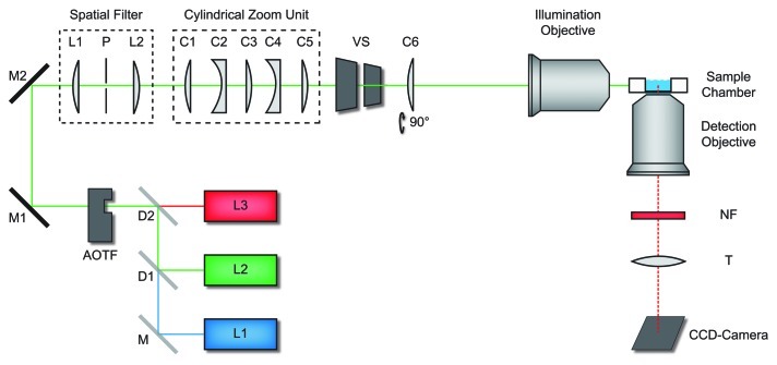
Figure 1. Light sheet fluorescence microscope. Light from various laser sources (L1 - L3) was directed into the illumination beam path via dichroic beam splitters (D1 and D2), and mirrors (M, M1, M2). Laser source and intensity was controlled by an acousto-optical-tunable filter (AOTF). Two achromatic lenses L1 and L2 (f = 30 mm) and the pinhole P formed a spatial filter. A cylindrical zoom unit comprised five lenses (C1 - C5). The cylindrical lens (C6) oriented perpendicular to the zoom lens unit focused the beam into the back focal plane of the illumination objective, which generated the light sheet in the sample chamber. A vertical slit (VS) controlled the width of the light sheet. The sample can be moved by a motorized sample scanner. Fluorescence detection was performed by the detection objective, a set of notch filters (NF), the tube lens (T) and an electron multiplying CCD-camera. Figure according to Ritter et al.18

An official website of the United States government
Here's how you know
Official websites use .gov
A
.gov website belongs to an official
government organization in the United States.
Secure .gov websites use HTTPS
A lock (
) or https:// means you've safely
connected to the .gov website. Share sensitive
information only on official, secure websites.
