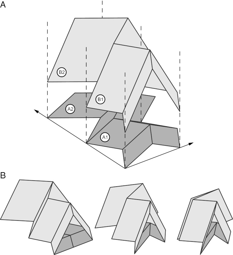
Fig. 7.
The unit cell geometry of the Miura pattern can be varied within each layer. A shows layer A with unit cells A1 and A2, on which are stacked unit cells B1 and B2 in layer B. The relationship between the unit cell geometries is given by Eq. 21. The geometry γA2 < γA1 is selected such that unit cells A2 and B2 will lock in a predetermined configuration, which is shown in B.

