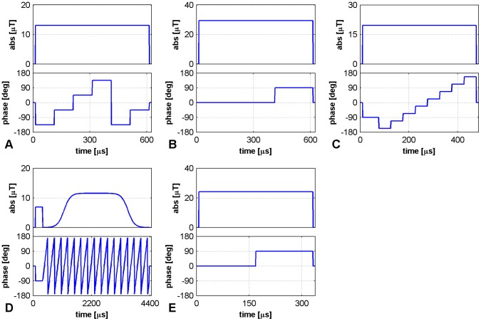
Figure 1. RF-pulse envelopes for phase-based B1+ mapping.
Diagrams of the composite pulses used for all methods: A – Optimized low-flip-angle method , B – Phase-sensitive method , C – ΦFA-CUP method , D – Bloch-Siegert method, E – Orthogonal-pulses method. Pulse timing, intensity of the B1+ field (in µT) and RF-phases (in degrees) are sketched. The parameters used are: A) α = 20° and duration of 600 µs; B) α = 90° and duration of 600 µs; C) p0 = 20°, α = 15° and duration of 400 µs (plus the duration of the p0 pulse); D) p0 = 20°, α = 425° and duration of 4000 µs (plus the duration of the p0 pulse); E) α = 60° and duration of 325 µs.

