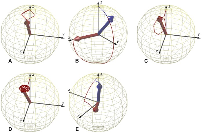
Figure 2. Trajectories of the magnetization during RF-excitation.
Evolution of M in a unitary sphere during the RF-pulses of Fig.1 (red lines), under ideal conditions (ΔB0 = 0) for all methods: A – Optimized low-flip-angle method , B – Phase-sensitive method , C – ΦFA-CUP method , D – Bloch-Siegert method, E – Orthogonal-pulses method. A) a squared trajectory is traversed for one and a half turns; B) for small flip angles a rectangular trajectory is traversed for half turn (blue line: α = 18°), the flip angle originally proposed moves M into the transverse plane (red line: α = 90°); C) an intial pulse moves M far from the origin, then an octagonal loop is traversed for one turn only; D) an initial excitation is followed by an off-resonance pulse, which is equivalent to traversing a circular trajectory for several turns; E) for small flip angles a square trajectory is traversed for half turn (blue line: α = 12°), the flip angle originally proposed moves M close to the transverse plane (red line: α = 60°).

