
Figure 3. A switch between dep2 and dep1 stationary states triggered by a short hyperpolarizing pulse of current.
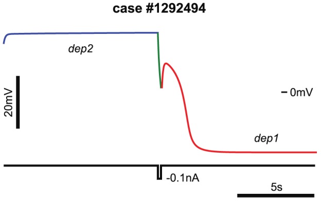
These states correspond to two states of excitability block. The case (#1292494) leak conductance in the database is 14 nS. The value used,  = 0.5783 nS, is taken from the interval of coexistence of the dep1 and dep2 branches of stationary states, denoted by a red brown bar in Figure 2C. The model was started near the dep2 stationary state (blue line), and was perturbed with a square pulse of current after 10 s (green line). The amplitude and the duration of the pulse were −0.1 nA and 0.2 s, correspondingly. The red line depicts transition of the neuron into dep1 state.