Abstract
Several challenges await new assistant professors setting up a neuroscience lab, and obtaining sufficient research help is typically a top priority. A secondary, but no less daunting, challenge is juggling accuracy and reliability with costs and limited start-up funds. These concerns are particularly crucial for those engaging technically sophisticated measurements, such as microdialysis. We have developed straightforward procedures that our undergraduate students have utilized to successfully construct high-quality, low-cost microdialysis probes. Students mastering the various steps involved have also gained valuable insight into their use, troubleshooting, and the implications of data obtained from these constructed probes. These procedures are explained here to foster increased use in neuroscience labs that involve undergraduates, along with pointers about teaching the technique to newcomers. Students who master the techniques can pass them on to new students easily. These procedures train students in the overall research technique of microdialysis more thoroughly than when manufactured probes are used, they save money, and will eventually save the principal investigator time when students develop independence with troubleshooting and repairs.
Keywords: microdialysis, in-vivo, freely-moving, probe design, undergraduate pedagogy
INTRODUCTION
The neurochemical measurement technique microdialysis has been reviewed extensively elsewhere as to both theory and history (Benveniste and Hüttemeier, 1990; Tisdall and Smith, 2006). Several techniques have been used to measure neurotransmitters that have either fallen short, or continue to be used for various reasons. Microdialysis remains a popular and current technique. Neuroscience investigations using microdialysis as the sole or central measurement technique initially surged between 1989 and 1991, essentially doubling in number during this time, leading to the beginning of a major upswing in publications (Robinson and Justice, 1991; Robinson, 1995). According to Medline®, cumulative articles with microdialysis as a keyword have been increasing at a fairly steady pace over the past 29 years (see Figure 1; Medline). Although microdialysis investigations were by no means limited to neuroscience (Robinson, 1995), the large majority of these articles came from neuroscience labs during the surge in 1992 through present day (Figure 1; Medline). The authors’ combined experience with heavy undergraduate involvement in microdialysis-related neuroscience investigations leaves no doubt that these procedures are entirely accessible at all collegiate levels. It is more challenging to assess undergraduate student involvement in neuroscience labs that use, or have used, microdialysis as their main research technique. Often when new faculty recruits begin at a university, even in situations where both graduate and undergraduate neuroscience programs exist, they will need to rely on assistance from undergraduate students. The bulk of initial work will be accomplished with the help of undergraduate students who volunteer, take lab-focused research courses, or get paid as work-study. While neuroscience microdialysis projects are typically large endeavors involving sensitive procedures, surgery, and a number of technically demanding steps, our laboratory has regularly involved undergraduates in essentially every procedure without diminishing the quality of workmanship. One aspect of our microdialysis research that has been consistently successful and of great benefit has been constructing microdialysis probes from raw materials in the laboratory as opposed to purchasing ready-manufactured probes from the various available sources. Rather than trying to use manufactured probes repeatedly, we find that following a rather simple pattern to construct microdialysis probes within the lab saves money and minimizes risk of failing probes. The key advantage of lab-constructed probes is the ease of replacing the membrane once the overall skeleton has been constructed. This allows experiments to be done with fresh membranes at every probe insertion, virtually eliminating decrements in recovery due to repeated use.
Figure 1.
The inclusion of “microdialysis” as a keyword in a Medline search reveals a broad range of articles and an increased use of this technique during the past 29 years.
Undergraduate students can learn to make these microdialysis probes, and as their skill in this construction process improves, they gain valuable insight into the way these probes work, the rationale of their construction, appropriate quality control, and intelligent strategies of troubleshooting their use. While other probe-constructing instructions have been generated (Pettit and Justice, 1991; Jolly and Vezina, 1996), neither provided a simplified method that was sufficiently accessible to undergraduate students. We felt that a clear method should be provided to enable other labs to benefit, without the complications of an underdeveloped system or highly technical jargon so that undergraduates could begin producing useful and practical probes quickly. We feel strongly that involving students in the earliest stages of probe construction is helpful in multiple ways, making it a worthwhile endeavor for both new and established microdialysis labs. It keeps the burden of probe construction off the shoulders of the principal investigator, promotes a sense of personal ownership of data obtained, and eventually produces teachers out of students in an entirely straightforward and stepwise process. Student independence in the research procedures and exposure to the probe construction process increases their capacity to pinpoint and repair the inevitable problems that occur with any microdialysis probe system. Learning probe construction is likely to give undergraduate students a competitive edge when working as graduate students in labs performing microdialysis-related experiments. It would also render a student more useful to a graduate program or company (labs using microdialysis) even if that lab typically purchases their own probes. Troubleshooting manipulations of any make or model dialysis probe becomes far more obvious when a student works with probe construction regularly, even if purchased probe designs often thwart corrective measures. Therefore, students can learn advantages of specific design features and make better choices when called on to do so in their career. Also, when many people working with a lab know every step, each can pick up where others left off very easily and more probes are created, tested, and ready for use in experiments efficiently.
CONSTRUCTED PROBE QUALITY
The microdialysis probes described here have been used to measure glutamate levels in adult rat striatum (Sandstrom and Rebec, 2007), and with 4.0 mm membrane tips they yielded recoveries of 8–14% when tested in-vitro submerged in 75μM glutamate at 2 microliter/min artificial cerebrospinal fluid (aCSF) flow. Our current probes are constructed the same way with smaller cannula length for mice and 3.0 mm membrane tips range between from 7–12% recovery of the monoamines we are currently measuring. These are comparable with the advertised recoveries of most manufactured probes.
These probes rarely clog or leak and they are resilient enough to withstand fluid flow rates of up to 8 microliters per minute (so they can be quickly saturated with aCSF prior to experiments). When constructed properly, a probe skeleton can be recycled at least five times with careful handling. When probe skeletons are recycled, changing probe membranes is the only major constructive manipulation necessary prior to re-use. This eliminates the need for constant production of new probes from scratch, as a new probe and a newly changed membrane on a recycled skeleton will harbor the same desirable qualities.
Component cannula parts can be cleaned and re-used regularly, at least five times beyond their new state and likely more with careful handling as old membranes are burned off the base. Each batch of membranes purchased typically provides sufficient supply for at least a year, covering all probes needed in multiple experiments during that time (see Table 1 for acquisition information). Despite an approximate $100 initial up-front cost, each package of 20 fibers allows for the production of probes at a much reduced cost. Such probe construction also circumvents design flaws inherent to several existing manufactured probes that either lead to increased risk of clogging, cracking, and leaking, or prevent simple corrective measures for those problems that are possible with our design. No probes on the market today allow for skeleton recycling and membrane replacement. One popular brand has membranes attached on the outside of the infusion cannula shaft, and this increases the risk of the probe membrane getting caught on the guide cannula during removal. If this happens, the cellulose membrane remains lodged in the subject’s tissue upon probe removal, preventing any second dialysis session and compromising the animal among other problems. Such pitfalls are all avoided with the construction style we advocate below.
Table 1.
Common supplies and vendors
| Item | Vendor | Acquisition Information | |
|---|---|---|---|
| 1 | Fused silica tubing | Polymicro Technologies (Phoenix, AZ) | Part# 2000018, TSP075150, OD-150, ID-75 (keep output OD near 150, but input OD can increase up to 170 often easing flow) |
| 2 | Internal infusion cannulae | Plastics One, Inc. (Roanoke, VA) | 26ga, C3121 (length of plastic pedestal for mice 5.0mm, for rats ∼8.0mm, typically we use 0.1mm extension beyond guide cannula – see below) |
| 3 | Guide cannulae | Plastics One, Inc. (Roanoke, VA) | 21ga, C312G length of stainless steel below pedestal for mice. We use 2.0mm, for rats ∼11.0mm, (adjustable, plastic pedestal height 8.0mm standard for rats, 5.0mm pedestal height for mice). |
| 4 | Dummy cannulae | Plastics One, Inc. (Roanoke, VA) | C312DC (0.46mm thick wire used as this is the outer diameter of the internal cannulae above) C312IDC (implantation dummy fits under typical stereotaxic arm devices, MH300, contact Plastics One for stereotaxic device for your apparatus). |
| 5 | Connector Assembly | Plastics One, Inc. (Roanoke, VA) | C313C or C313CS for plain vinyl or stainless steel spring covered respectively. We recommend C313C for mice and C313CS for rats. Specify length per application. We currently use 20–21cm within mouse operant chambers (Med Associates; St. Albans, VT). You won’t need the inner tubing. |
| 6 | Polyethylene tubing | Clay Adams (B&D); Thomas Sci. (Swedesborough, NJ) | PE10 (427401), PE50 (427410), available from most standard vendors such as Fisher or VWR. Purchase longer lengths of the PE10; you’ll only need small amounts of PE50. |
| 7 | Semi Permeable hollow cellulose microdialysis | Spectrum (Houston, TX) | Their Spectra/Por® In vivo Microdialysis Hollow Fibers work great at a molecular weight cut off of 18,000 Daltons. They come in 20 strips of 6”. Produce 132295. http://spectrapor.com/dialysis/InVivo.html |
| 8 | Tubing connector adaptors | CMA Microdialysis (Chelmsford, MA) | 0303409500, little blue adaptors come 10/pkg. |
| 9 | 2-ton Epoxy | Devcon, Division of ITW Performance Polymers (Riviera Beach, FL) | Best by far has “2 Ton Epoxy All Purpose” on the label, part# S31/31345, Working time – 0:30 mins., Handling time – 2:00 hrs. |
PROBE CONSTRUCTION PROCEDURES
In preparation for building microdialysis probes, it would be best to acquire the various required component parts and tools (listed in Tables 1 and 2 respectively), and designate some workspace for the construction process. It is also best to wear some sort of protective glove throughout this construction process (latex, nitrile, Teflon). The gloves will keep any oils from your skin from seeping into junctures or getting into the tubing. When working with the fused silica tubing, it is also a good idea to wear protective eyewear to prevent accidental eye injury (safety instructions: Polymicro Technologies silica).
Table 2.
Tools needed for probe construction
| Item | Vendor | Acquisition Information | |
|---|---|---|---|
| 1 | 26-1/2 gauge needles | Becton Dickinson [B–D] (Franklin Lakes, NJ) | Reorder-305111, tan colored |
| 2 | Straight stainless steel razor blades or scalpel blades | Any hardware store single-edge blades | Keep an eye on these as if exposed to ethanol or ungloved skin oil they may start to rust. Used primarily to cut tubing to length. |
| 3 | Parafilm M | Any scientific vendor | Small amounts typically needed so we recommend either the 5 or 10cm width (e.g. VWR Cat# 52858-076). |
| 4 | Good quality small pair stainless steel scissors | Typically available from arts & crafts store or cuticle scissors | We are currently using a small pair of straight blade cuticle scissors. Be sure there is no blade gap or minimal gap. |
| 5 | Masking tape | Any hardware or department store | e.g. Scotch 2308, typically 1-inch width |
| 6 | Magnifying glass clamp | Department stores and can be found online for under $10 | Useful for the various gluing and membrane insertion steps. See Figure 7B for image. |
| 7 | Swiss Jeweler forceps | Miltex (Bethpage, NY) | Style 5 superfine Miltex Cat#17-305 or equivalent. Can also use titanium if you prefer. |
| 8 | Fine grain sandpaper | Something like 3M Hardware store | We use 3M 413Q 400 Wetordry Tri-M-Ite™ Paper A Weight. |
| 9 | Vernier calipers | Any good hardware store | Be sure these are metric scale. Often metal ones provide a more accurate line. |
Although some application-based modifications will be described at the end of this article, other modifications are possible for more sophisticated applications. For example, the length of cannulae, probe membrane tip, and connector assembly can certainly be modified to accomplish dialysis in different brain regions or different venues (e.g. dialysis bowls versus operant chambers).
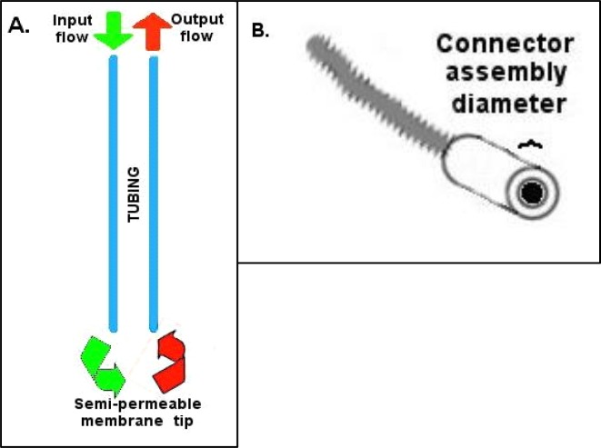
Every time epoxy is used to bind various tubing components together in these procedures, it is possible the epoxy will bead or form droplets on the exterior of the tubing. Care and attention should be directed at wiping these away, as the combined tubing will eventually need to fit through the inner diameter of a connector assembly. With each epoxy addition step (e.g. Steps two and five) the buildup of epoxy should be carefully controlled to allow only a thin layer on the outside of any polyethylene tubing that will eventually need to penetrate into the connector assembly (see #5 in Table 1, and Figure 2B).
Figure 2.
A. Basic probe flow design, B. Connector assembly inner diameter restriction
The basic probe tubing skeleton will require using the epoxy to seal together several different pieces of tubing. It is important to keep track of which tube is which, particularly if you elect (as we do) to go with a wider diameter input fused silica (see #1 Table 1) than output silica. During the remainder of these instructions the input will refer to the tubing that will deliver fresh aCSF to the probe tip, and the output will refer to the tubing that will deliver efflux containing diffused compounds of interest towards the collection destination (see Figure 2A). In this probe design, the output tubing will include a narrow fused silica central core because this reduces delays caused by the collection of dead mobile solution volume within the probe hardware. This central core also acts as a sort of skeleton for the membrane tip to keep it stiff enough to penetrate the tissue upon probe insertion.
Considerations such as the length of guide or infusion cannulae (see #2 and 3 Table 1) should be made based on the animal model, and corresponding ventral location of your region of interest (ROI). These determinations can be made after determining depths involved and the dimensions of ROI nuclei.
Step One
Cut two equal lengths of PE-10 polyethylene tubing (see #6 Table 1). These two lengths will represent the input and output of your probe assembly and so it is important to measure these according to the length of your C313C connector assembly. Typically the connector assembly (see #5 Table 1) length is selected based on the intended experiments. Standard CMA Microdialysis bowls (830 9031 CMA; Chelmsford, MA) work well with the standard length of 40.0 cm provided by Plastics One, Inc. Cutting about 3.0 cm extra length than the connector assembly is usually sufficient. Some length can be tailored off after the whole probe is constructed. Match two of the ends together on one side and rub them against fine grain sandpaper (see #8 Table 1). Ideally, render at least 2.0 cm at the end of both tubing length rough with the sandpaper. While sanding, be careful not to stretch the tubing (effectively decreasing its inner diameter) at any time such sanding is necessary (Step three). This step is important to allow the epoxy to hold on the tubing sufficiently and folding the sandpaper over the two ends and rubbing back to roll the ends against each side will accomplish this. After the tubing is sufficiently rough, match the ends together again and tape them against the counter edge as shown in Figure 3. Here it is important for the ends to be touching each other “like a zipper.” At this point, put a small indelible ink mark (use any dark color Sharpie pen) on one of the PE-10 tubes both above and below the tape, with the mark below the tape preferably close to the opposite end. This marked tube will now represent the input tube.
Figure 3.
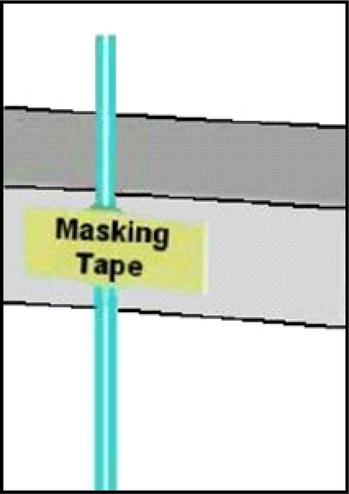
Tape lengths of PE-10 tubing against the bench counter so the sanded ends extend equally and tightly together above the counter. Place tape slightly below the rough area.
Before using any epoxy, cut lengths of fused silica tubing for the input and output (see #1 Table 1). We use two different outer diameters of fused silica (input = between 162 and 168, output = 150) and you can request any sizes when purchasing. The rationale of using larger diameter for the input is that the larger diameter tubing is far less likely to lead to clogging over repeated use on the input side (important when looking at some manufactured probes that use large amounts of fused silica tubing). It is quite possible to use only OD-150 tubing as described in Table 1. Cut silica tubing with a razor blade against a glass microscope slide, being careful to control the cut piece as these are hard to pick up if they fly away. The output silica tube should be cut longer than the input tubing. In part, the length of the output tubing is determined by the length of the metal shaft of the infusion cannula that will act as the extension shaft of the dialysis probe (see #2 Table 1). Typically at this point about, 7.0 cm of output tubing and 5.0 cm of input tubing will work fine. Place about 1.5 cm of each silica tube into each PE-10 tube, being sure to put the input sized silica into the PE-10 tube you’ve marked with ink to designate it as input. After inserting these lengths it is convenient to place a very thin (5.0 mm thick x 3.0 cm long) strip of Parafilm pinched over the top of the small input silica and around the output length to hold the silica lengths so that they touch each other (see Figure 4).
Figure 4.
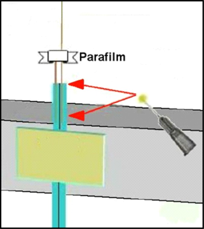
Apply to the PE-10 tubing rough area as well as about 1.0mm onto fused silica, then push the fused silica down to carry epoxy inside PE-10 tubing.
Step Two
Mix the epoxy now (approximately 0.5 ml of each component necessary, small amount, ideally on a disposable surface like the back of a plastic weigh boat) so that it just begins curing and apply sparingly around the roughened area of the two PE-10 ends, and slightly above these to touch the fused silica below the Parafilm (see Figure 5). When epoxy is placed about 1.0 mm above the top of the PE-10 tubing, push the silica into the PE-10 together so that the epoxy is carried inside the PE-10 tubing. It is best to have about 1.0 cm of internal seal like this along with the outer seal to ensure that the fused silica is fully united with the PE-10 tubing. Be careful also to scrape off excess epoxy so that it doesn’t bunch up or form droplets before curing (recall this needs to fit inside the connector assembly). The brand of epoxy we recommend (see #9 Table 1) typically takes about 2 hrs. to fully cure at room temperature.
Figure 5.
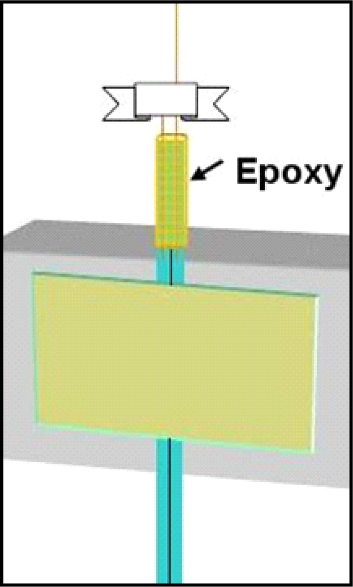
Epoxy coating with a thin layer on the outside barely visible, with seal entering the PE-10 tubing. After curing, pull the Parafilm off by pulling the ends apart like untying a shoe.
Step Three
This step requires a bit of length determination. Also, you’ll need the infusion cannula selected for your ROI. New infusion cannulae often have edges that face inwards that interfere with membrane insertion (Step five). To avoid this problem, it is best to “ream” the infusion cannula with the end of a 26-ga needle. Simply put the needle tip into the output end of the infusion cannula and twirl it back and forth between thumb and forefinger several times. Think of this as, in effect, widening the output end slightly (though any actual end widening is negligible). To measure the appropriate length of PE-50 tubing, insert the white plastic end of an infusion cannula (see #2 Table 1) all the way into the PE 50 tubing before you cut it. Inserting this plastic end can be made easier with a small drop of ethanol on the white plastic collar. When using ethanol to help with infusion cannula insertion ensure that the ethanol evaporates prior to epoxy application as it can compromise epoxy binding. Line this up beside the tubing skeleton thus far created so that the inside white end of the infusion cannula sits about 2.0 mm above where the input silica ends, and make a mark on the PE-50 tubing where it lines up with the PE-10 tubing. Typically by now you want about 3.0 cm of input silica length extending above the PE-10 tubing (see Figure 6, dotted line where you line up by eye). After cutting the length of PE-50 below the infusion cannula at the mark you make with a razor blade, use the fine grained sandpaper to rough the free end of PE50 on the outside as shown in Figure 6.
Figure 6.
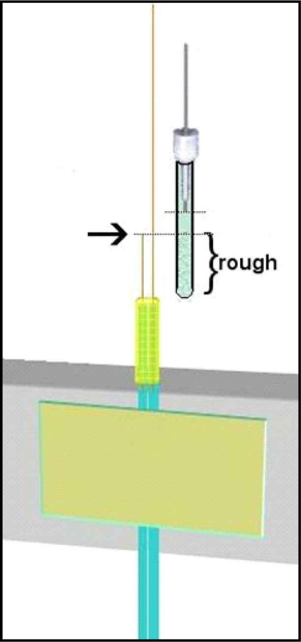
Determine length of PE-50 based on input silica. Bracketed area should be sanded and rough. Dotted lines represent top of input silica and bottom of infusion cannula. Notice the space between these (about 2mm). Mark and cut, then sand to rough before epoxy step.
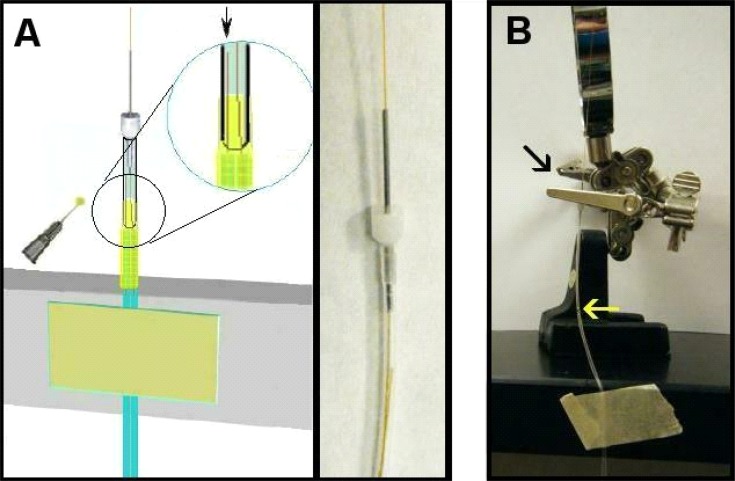
Place the PE-50 tubing over the extended output silica tubing such that the output silica enters the PE-50 tubing first, goes through the infusion cannula, and exits the other end of this cannula (where the probe tip will be). Many students find this challenging at first because the silica tubing needs to find the entrance of the infusion cannula, so patience is needed and it is imperative that the infusion cannula and PE-50 tubing be kept straight during this insertion. Next mix another small amount of epoxy and with a needle place a small dab 1.0–2.0 mm above the top of the PE-10 tubing on the two fused silica tubes so that it expands outward in a droplet. Slide the PE-50 tubing down onto this epoxy you just placed such that some epoxy enters the inside of the PE-50 tubing. Next coat the rough end of the PE-50 with a thin layer of epoxy (sparingly on the outside to keep the end product narrow). It is important to avoid allowing the epoxy to seep above the inner input silica tubing as this will block flow and destroy the probe. If this happens, you need to start over, so be careful when pushing the PE-50 tubing down onto the epoxy (see Figure 7A).
Figure 7.
A. Inserting PE-50 and cannula. Magnified insert shows position of internal silica tubing. The arrow points to the input (short) silica end that should remain well above the epoxy when you slide on the PE-50 tubing. Hold in place until epoxy cures. Photograph to the right shows input silica below infusion cannula inside PE-50 tubing. B. Holding the PE-50 tubing down against the epoxy seal until it fully cures. Black arrow points to where cannula simply slides through hole in closed clamp rather than clamping down on shaft. Bright yellow arrow points to epoxy union kept tight to keep PE-50 tubing against PE-10 tubes representing input and output.
It may be necessary to hold the cannula part down as this epoxy cures so that the union between the PE-50 and PE-10 tubes is minimized (easily done with one of the clamps from the magnifier clamp, see #6 in Table 2). This is because if the silica tubes are not as close together as possible they will try to separate and push the PE-50 tube upwards (see Figure 7B).
Step Four
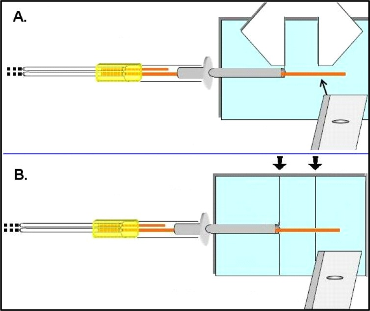
In this step the inner skeleton of the probe tip is cut to the desired length. This length is selected based on the nucleus/ganglia dimensions your experiments are designed to sample. For example, typically a rat dorsal striatum experiment can accommodate a 4.0 mm probe while a mouse dorsal striatum would accommodate a 3.0 mm probe length. It has been stated above that considerations such as the ventral depth of your region of interest (ROI) are an important part of selecting guide and infusion cannulae. It is important to be sure the infusion cannula is sitting firmly within the PE-50 tubing as shown in Figure 8 when making this cut. Use a microscope slide with a frosted or labeling side and draw two thin lines with a gap between them exactly the distance of your desired tip length (measure with Vernier calipers Table 2 #9, see Figure 8A). Line up the metal end of the infusion cannula with one line, and cut the fused silica tubing at the other line (see Figure 8B).
Figure 8.
Measuring and cutting the probe tip length. Use vernier calipers to measure desired length for your region of interest (A), and once a standard length is established, draw guidelines on a glass slide to standardize this process – arrows represent desired distance (B). Cut with razor blade against a glass slide. Avoid touching the output tubing with ungloved fingers.
Step Five
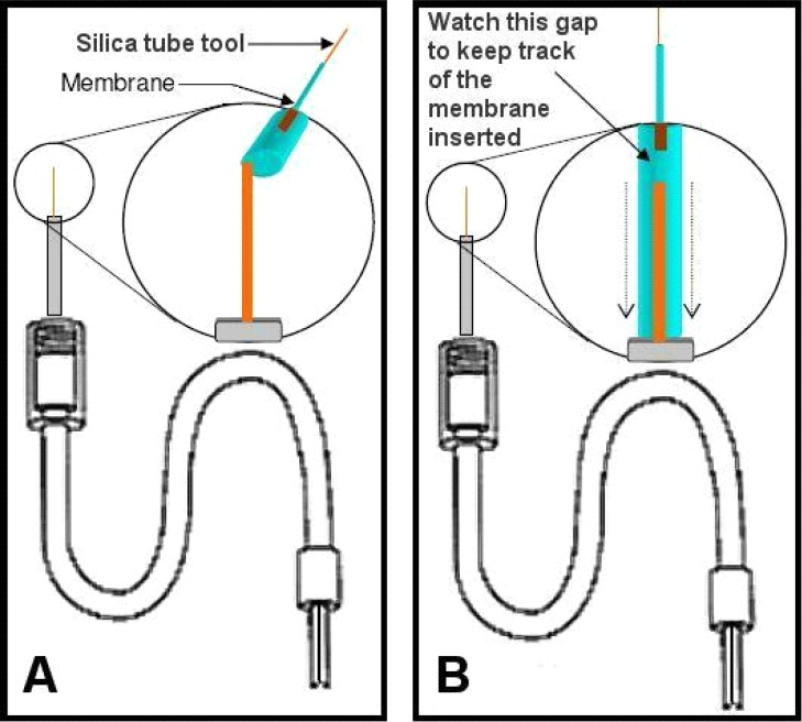
After cutting the output silica probe tip to length it is typically useful to thread the now partially-constructed probe tubing (the PE-10 input & output) into the connector assembly (see #5 Table 1). Thread these into the connector assembly end that turns to screw onto the guide cannula and push the joined tubing through the connector assembly until it extends through and out the other end. If length was measured according to the connector assembly as suggested, the PE-10 tubing should come out at least an inch from the other end with one end marked (input). The membrane (see #7 Table 1) will now be added to the probe. Note that after the overall skeleton is made (above Steps one through four) it is easy to replace membranes on probes (see the end of Step six for further discussion of this). The easiest way to control membranes is to slide them over lengths of fused silica tubing, so a series of fused silica “tools” (referred to as “silica tool”) can easily be made by cutting lengths of approximately 12.0 cm of the 150-OD fused silica (used with the output). These lengths can be kept with their ends stuck into foam padding or a sponge until needed. Use a magnifying glass to put a 4.0 cm length of membrane (a fragile but semi-stiff tube, best to keep straight) over the end of one such tool to prepare for this step (Figure 9). Push the membrane onto the silica tool until about 4 cm covers its length and cut off the membrane with a pair of clean scissors (see #4 Table 2). Then extend the membrane from the silica tool tip about 1.0–1.5 mm. Attach the connector assembly to the magnifier clamp apparatus so that you can clearly see the output fused silica (cut in Step four) extending upwards behind the magnifier. The subsequent goal is to ease the membrane inside the metal infusion cannula, but over top or outside the output fused silica that extends from within the infusion cannula. This happens easily if the output ends of any new infusion cannulae have been “reamed” prior to insertion (described at beginning of Step three). As you insert the membrane, it will eventually be hidden inside the infusion cannula so the most common question is “how do you tell how far you’ve inserted the membrane inside the infusion cannula since the membrane is clear?” The answer is that we track membrane insertion by monitoring the distances the silica tool has moved in proximity to the fixed silica on the probe each time you advance the membrane (pulling the silica tool back when more membrane is needed). Pinch the membrane itself between thumb and forefinger to advance the membrane, and then while still holding the membrane in place, pull the silica tool upwards to create another small gap, and so on. The membranes (see #7 Table 1) come in 20 strips of 6-inch lengths coated with a sugar that keeps them partially stiff. It is best to insert membranes while the overall apparatus is dry so that you can take advantage of the stiff coating to push the membranes into the infusion cannula. If the membranes get wet, they become very pliable which is good for dialysis but not for installation (see Figure 10).
Figure 9.
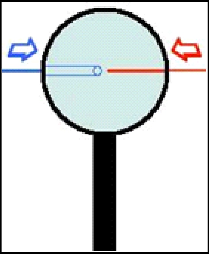
Fitting membrane tool silica (depicted in red) into membrane tube (depicted in blue) over desired length. Slide fused silica inside membrane tube.
Figure 10.
A. Use silica tool to place membrane over output silica on probe. B. Push membrane deeper inside infusion cannula (insert to cover half the infusion cannula length). Track distance via gap between silica.
This step typically requires practice, and students find it challenging to steady their fingers while first easing the membrane onto the probe-associated output fused silica. Once this step is mastered, students usually refer to the other steps as easy by comparison. Keep track of the amount of membrane placed inside the infusion cannula by watching the gap between the silica tool and the probe-associated silica (top and bottom silica in Figure 10B), eventually these will touch each other. Push enough membrane into the infusion cannula this way until half of the total infusion cannula length is covered. If more membrane “slack” is needed hold the membrane just above the infusion cannula and pull the silica tool back a bit more until this is accomplished. At this point there should be sufficient membrane inside the infusion cannula to apply epoxy, though not so much that the membrane extends beyond the approximate midpoint of the cannula (you will need to push the membrane in further once epoxy is applied). Mix another small amount of epoxy and apply very small droplets just above the end of the infusion cannula (mostly on the membrane itself, just below the two arrows in Figure 10B) with a 26-ga needle so that one continuous droplet seems to sit just atop the metal infusion cannula. Then, while the epoxy remains uncured, begin pushing the membrane further into the infusion cannula, essentially carrying the epoxy into the infusion cannula (between the inside of the cannula and the outside of the membrane). You should only need to push down approximately 3.0 mm to carry sufficient epoxy into the cannula to maintain a good seal. After pushing the membrane in like that use the same needle to collect remaining epoxy. Make a small wick by curling or twisting the corner of Kimwipe®, and use this as well to wipe excess epoxy off the outside of the infusion cannula. After performing this cleaning step push the membrane into the cannula the last small amount necessary until the visible epoxy disappears into the cannula tip (Figure 11). After performing this step it is necessary for the epoxy to cure for at least two hours if you use the brand we recommend, or sufficiently to maintain the bond otherwise. If equal amounts of each epoxy component were sufficiently mixed, this curing time should allow the bond to form the necessary seal. Once the epoxy cures, take the scissors (see #4 Table 2) and cut the membrane approximately 0.5–0.7 mm above the output silica so that you can still see through the clear membrane (see Figure 12). Keep the silica tool inserted into the membrane during this step, simply pulled back, as this will allow preservation of the remaining membrane for a subsequent probe. The distance beyond the silica that you make this cut will translate into the amount of membrane tip that should be filled with epoxy when you seal the membrane tip. Depending on the ROI, keeping this distance very small may be desirable to avoid poking into regions where blood vessels may travel at the ventral surface of the brain, and also to minimize damage to regions outside your ROI. Approximately 0.5 mm is necessary to create a sufficient seal at the membrane tip.
Figure 11.
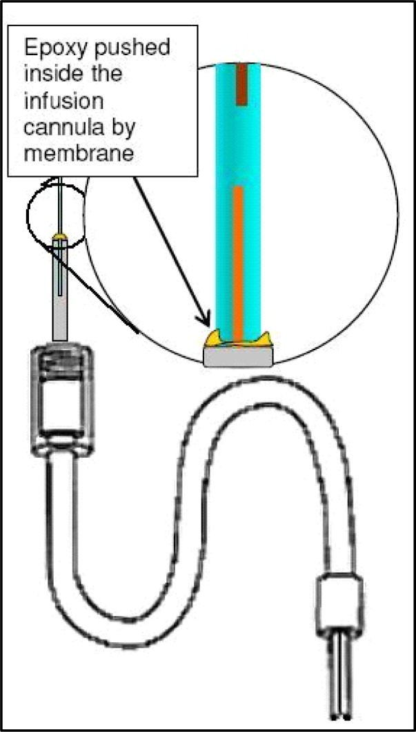
After epoxy is added, push it inside infusion cannula (carried on membrane) and wipe off excess epoxy that gets onto outside of metal shaft.
Figure 12.
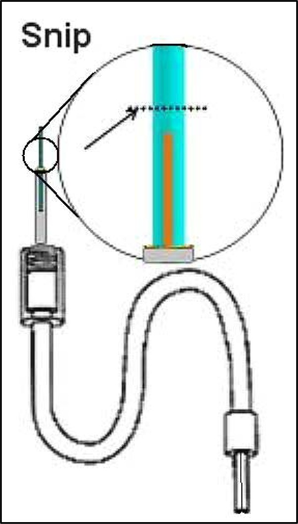
Cut the membrane and remember distance from silica. This is the distance to be plugged with epoxy in Step six.
Step Six
Prior to plugging the membrane tip it is important to move the output silica away from the exposed membrane end to avoid getting epoxy into this silica. This is commonly considered a difficult step because the friction fitting of the guide cannula must be shifted from the inside of the PE-50 tubing while not breaking the output silica tubing. First time students typically break the output silica at least once before mastering this step. The infusion cannula must be eased partially out of the PE-50 tubing as shown in Figure 13.
Figure 13.
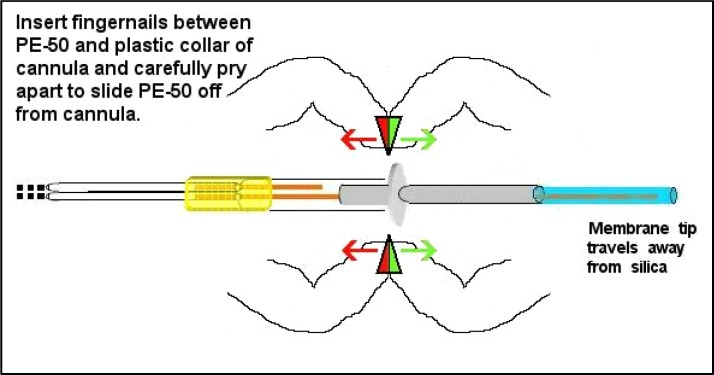
After epoxy curing the cannula can be eased out of the PE-50 tubing, but do this carefully as the silica tubing should not be bent or crimped during this step. Avoid stretching the PE-50 tubing length that will compromise the seal at this friction fitting following tip plug epoxy curing (see Figure 15).
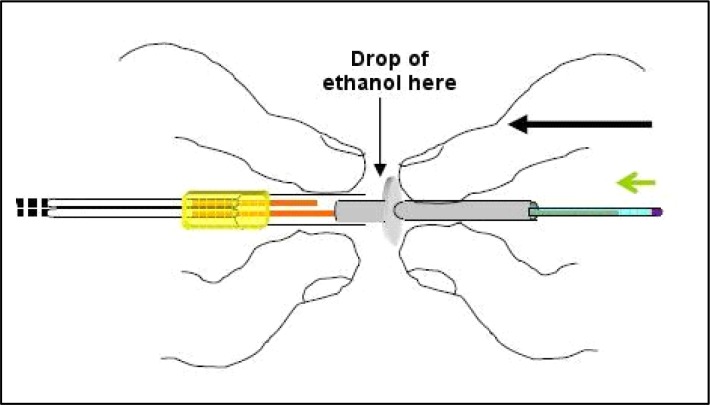
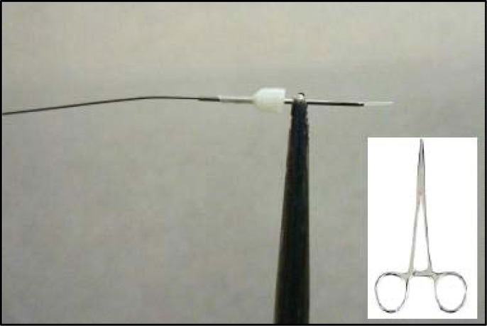
Although the distance between the inner silica and the membrane tip will expand, the amount of epoxy used to plug the membrane tip should only approximate the original distance before the cannula was shifted. Plugging the membrane tip should be performed while the probe is taped with the membrane facing down so that the epoxy (which will travel into the membrane via capillary action) is kept to a minimal region. Mix a very small amount of epoxy and with a small droplet on the end of a needle simply touch (quick light touches) until the epoxy travels into the membrane tip the desired amount (approximating the original distance between silica and membrane end). To perform this tip-plugging maneuver, tape the probe to the counter edge facing down and shine a flashlight up from below onto the membrane tip (see Figure 14). This will catch the droplet of epoxy and highlight it, as well as clarify how much epoxy has traveled into the membrane tip. Touch the epoxy to the membrane tip with quick light touches quickly moving it away after the touch so as to prevent capillary action from pulling epoxy up too far. Once the space approximating the original distance between the silica and membrane has been covered let this epoxy plug cure this way for at least two hours again. After the plug cures push the cannula back until the PE-50 tubing slides back up on the plastic portion as it was before, and ideally there will only be a sliver of distance between the silica and the hardened epoxy plug (see Figure 15). Placing a drop of 80% ethanol just in front of the PE-50 tubing before you begin to push with the flesh of your fingertips (not fingernails for this) will help this tubing slide more easily. This final step concludes the insertion of a new membrane. Following this, when a new probe is being made, you’ll need to put connectors onto the free end of the input line (at the other side of the connector assembly). If you are performing dialysis with dual-channel fluid swivels that allow you to channel output away to a fraction collector or collection vial outside an operant chamber you’ll need to put connectors onto both input and output PE-10 tubes protruding from the other side of the connector assembly.
Figure 14.
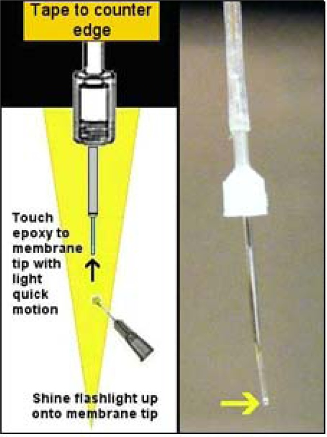
Plugging the membrane tip is done with probe facing down so that gravity counteracts capillary action. Keep epoxy plug as small as possible to ensure a full seal, covering distance the membrane was cut shown in Figure 12. Yellow arrow in photograph to right points to epoxy seal. Also notice fused silica pulled back above.
Figure 15.
To push the skeleton (output) silica back up into the membrane tip, use the flesh of your fingertips as shown while keeping tubing straight to avoid crimping the silica that goes through the cannula.
Following the use of this probe, replacing the membrane on a recycled skeleton, is as simple as pulling this old cannula completely off (membrane and all) with a motion described in Figure 13. This step requires that all liquid is blown out from the skeleton tubing and that the unit is dry. Typically, we remove old-used cannula, clean out the skeleton tubing with pure ethanol followed by air pushed through the lines (see pedagogical remarks), and finally replace the infusion cannula portion with a membrane-free cannula. Place a new infusion cannula by sliding it in until the PE-50 sits firmly around the plastic base, and proceed with the following step. New cannulae need not be completely new, but are typically used and cleaned (see below cleaning step). Insert a new cannula following the same motion described in Figure 15 (of course, this won’t have a membrane on it). It is important to keep the PE-50 tubing as straight as possible during the cannula replacement as the output tubing must also be threaded through the cannula. Bending the tubing too far will break the silica. After replacing the infusion cannula, go through Step five again. All infusion cannulae should be the same dimensions as they are ordered to specifications. When you push a new infusion cannula on, the output silica should protrude the same distance from the end. When replacing membranes, you need to thread the output silica through the infusion cannula and then be very careful to push the PE-50 onto the cannula with all the tubing kept as straight as possible. If you bend the tubing, you may accidentally crack the fused silica (basically pulled glass) inside the fused silica. If this happens, you’ll need to start again and construct another skeleton from Step one.
If a new cannula is being inserted during the process of recycling a probe skeleton after several uses, sometimes the PE-50 tubing is stretched or flared outward by the previous cannula and will not grip the new cannula. It may still be possible to recycle the skeleton by cutting slightly down into the end of PE-50 tubing that typically grips the cannula. Take a pair of sharp-tipped scissors and cut about three small 1.0 mm slices into the PE-50 opening while the infusion cannula is removed. These slices should proceed along the length of the PE-50 so that the little flaps of stretched PE-50 tubing can be splayed out (see Figure 16). Cut these flaps off with the scissors to reduce the overall length of the PE-50, and to allow the infusion cannula to push into fresh PE-50 tubing for a tighter seal as described above. If the input silica (inside the PE-50) is too close to the end inside, this correction should not be attempted as trapping the input silica against the side with the plastic portion of the infusion cannula will compromise the probe.
Figure 16.
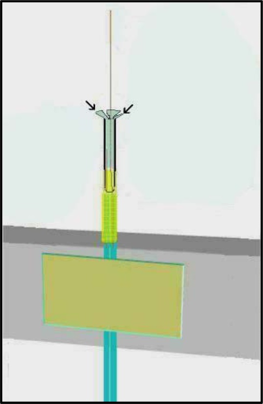
Slice into the PE-50 tubing with sharp pointed scissors with no blade gap at approximately three locations to create flaps, splay the flaps, and trim as needed to reach a portion of PE-50 with tight seal potential. Do this only after PE-50 becomes stretched after repeated uses and recycling.
Step Seven
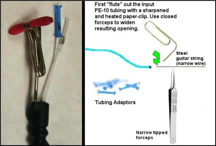
Placing connectors (see #8 Table 1) onto the PE-10 tubing requires a slight manipulation to the original polyethylene tubing because it is too narrow for the tubing adaptors to grip securely and prevent leaks otherwise. The rationale behind using PE-10 tubing rather than a larger caliber tubing that would allow the adaptors to grip without manipulations is that this minimizes dead volume as much as possible while still using a mostly pliable material such as polyethylene. Manufactured probes are sometimes made with fused silica completely (Plastics One; Roanoke, VA) or with larger caliber tubing (CMA Microdialysis; Chelmsford, MA). These probes work well, but their versatility is limited by either greater fragility or a larger dead volume respectively. Prior to putting connectors onto the ends of the PE-10 tubes, cut these ends down to only the length you need to reach the fluid swivel you use with the attachment style used, as this is another place where you can cut down on dead volume. Installing connectors is not dramatically difficult but also requires some practice and the creation of 3.0–4.0 mm lengths of 26-guage needle (see #1 Table 2). To cut these, we use a simple Dremel drill with a grinding wheel and needle-nose pliers (or curved hemostats can work). After short pieces are cut off, excluding the sharp end (typically you can get two or three from each needle at ½ inch length), “ream” these with a fresh needle while you still hold the 3–4mm length in the pliers. Obtain the most narrow steel guitar string you can find at a music shop (typically a steel E string that would be about 0.011–0.012). These are incredibly useful to have around and are usually amazingly cheap. Push this steel guitar string through the needle shaft, pulling back and forth to shave off any sharp bits, guiding it with the pliers. Remove the piece with the pliers and clean it by squirting 100% ethanol through with a common squirt bottle. Then insert the guitar string again so that the piece of needle is about 2 cm away from one end. Insert that guitar string end into the marked PE 10 tube (remember this is the tube representing your input line), and thread it into the PE-10 tube about 12 cm or so. The deeper you put the guitar string before pushing in the needle, the more careful you should be about the guitar string poking through the PE-10 tubing (a small hole half way down the input line can completely compromise the probe). Put some 100% ethanol into the end of this PE-10 tube and around the piece of needle you’re about to insert inside the PE-10 tube to allow it to slide more easily. Then begin pushing the needle piece inside the PE-10 tube with tweezers (guided by the guitar string, see Figure 17). This will cause the PE-10 tube to stretch wider and over the piece of needle, sliding it inside the PE-10, and expanding the outer diameter of the end sufficiently to allow the connector adaptors to grip.
Figure 17.
Store tubing adaptors in ethanol until use. After the ends of input lines have been prepared with the small syringe shaft insert, these will fit smoothly over the insert and dry to grip tightly on the tubing. Photograph to left shows installed connector adaptors. Notice the “T” connector made by straightening a large paper clip and wrapping one end about four times around an Alan wrench that approximates the outer diameter of the connector assembly input end to form a coil. The coil is then shrink-wrapped in place on the input side and the “T” is made to fit the liquid swivel connector that comes with Instech stainless steel fluid swivels (Instech Solomon: Plymouth Meeting, PA). Figure 18 shows attached assembly. See Figure 21 for a full-length blow-up.
While pushing, be careful that you keep the area of PE-10 tube surrounding the end of the guitar string straight, otherwise, this steel string will easily push through polyethylene and make a hole. Also, do not allow the PE-10 tubing to bunch up or “accordion” around the needle piece. Rather, slide the needle piece in smoothly so that the PE-10 tube wraps around it tightly. To make this whole step go more easily, there is a fluting procedure we often use that opens the PE-10 end wider at the tip. This is done with a sharpened paper clip (sharpen it with a nail file to develop a point) that is heated over a lighter flame and then touched on the tip of the PE-10 tube, slightly melting the end. Then we place very narrow (see #7 Table 2) needle-tipped forceps into the fluted end while they are closed to expand the end. Push the piece of needle shaft into the PE-10 tubing until it is flush with the end and be sure and cut off any “fluted” edges as these can cause the tubing adaptors to crack when they shrink down. Tubing adaptors (connectors, #8 Table 1) should be kept in 100% ethanol in a small air-tight container as they expand in ethanol. It is necessary for these connectors to expand prior to inserting the tubing as they will not insert otherwise. Ethanol-saturated adaptors can slide over these ends with needle-shaft pieces underneath, and they should be pushed on until the ends go half-way inside and then left alone for the ethanol to evaporate. As this occurs, they will shrink down and grasp the ends tightly for a good seal. It typically takes about five hours to fully dry and establish a good solid grip that prevents leakage if probes are left alone. A fan can speed up this step somewhat. It is important to keep the input and output of this probe distinct, even though the direction of flow should not affect overall recovery values, because the majority of the dead volume has been placed on the input side of the probe to promote the most efficient acquisition of efflux following diffusion at the membrane. Reversal of flow will introduce both delays and smoothing of neurochemical changes. Therefore, we leave markings indicating input on the probe even after construction is finished.
Testing Probes for Flow
After finishing dialysis probes and the epoxy completely cures, probes should be rinsed in slowly-stirring HPLC water for about 30 minutes to rinse off the sugar coating on the membranes. Although this sugar is biogenic, it will interfere somewhat with substance penetration and recovery. Following rinsing, these probes should be placed into holders (see Creating Probe Holders below) to keep them moist and ideally bacteria-free until use.
When the probe tips are stored in the holder, we recommend first testing the probe for flow. To do this, connect the input line to a syringe pump and begin pumping purified (HPLC-grade) water through the lines at between 2 and 5 μl/min. Given the standard 40 cm length of connector assembly, we have empirically determined the time taken for HPLC quality water to travel an 80 cm length of PE-10 tubing at 2 μl/min to essentially 15 min. Faster flow rates should produce droplets of water at the output tubing at shorter intervals given all seals are intact. The input and output PE-10 tubes will fill with water and eventually water will begin dripping from the output line. If there are clogs in any lines, this will be evidenced likely by the input-side tubing adaptor leaking or popping off from the syringe pump and PE-10 lines not filling. If lines fill but water never seems to arrive at the output line, there is likely a leak somewhere. Leaks typically occur at epoxy unions when epoxy does not slightly enter the component tubes creating a sealed union or when connections creep apart during the epoxy curing process (Figure 7B represents effort to prevent this). If the tube endings were sufficiently rough from sanding before the epoxy step, and people wear gloves during construction, these leaks will be minimal and rare. If you find leaks forming at the probe tip near the tip of the cannula, epoxy at Step five did not create a sufficient seal and you should follow the instructions under Step six for replacing membranes and re-do this step. Leaks at the most distal tip (Step six) mean that epoxy was not allowed inside the membrane sufficiently to grip and create a seal prior to rinsing the membrane. It is not possible to let the membrane dry again at this stage and re-apply epoxy, so you’ll have to replace the membrane again. While checking flow, remember the water must go somewhere if water is entering the input line. Check every union point for where leaks may be occurring.
Animal Surgery and Microdialysis Experiments
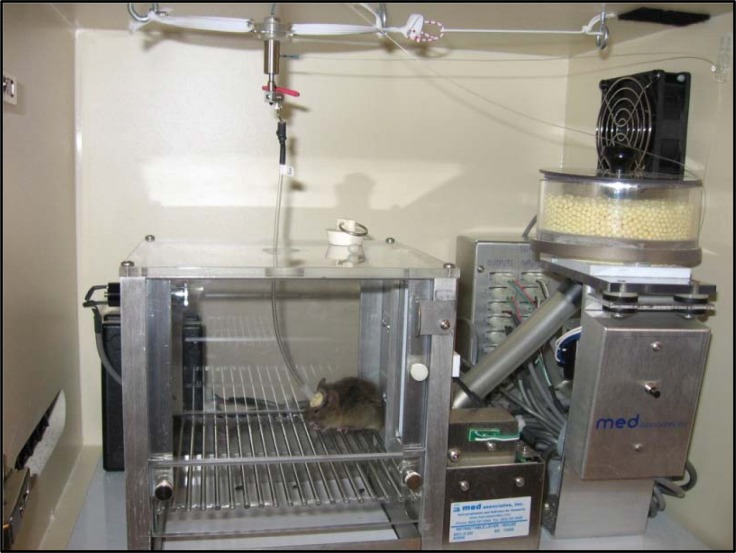
During survival surgery, insert the appropriate-length guide cannula (see #3 Table 1) intracerebrally terminating just dorsal to your ROI, attaching the plastic attachment port above the skull with small stainless steel screws and dental cement. We use Dentsply Caulk Grip Cement (Dentsply International; Milford, DE) because it can be easily chipped off the guide cannula after use to re-use these guides after removal. Following surgery, protect the targeted central region from debris with dummy cannulae cut to the same length as the guide (see #4 Table 1). Undergraduate students have mastered every step of these stereotaxic surgeries in our lab with both rats and mice and they claim these surgeries are the most attractive rationale for volunteering or taking a lab research-related course. Microdialysis is performed by simply inserting the constructed probe as you would an infusion cannula, and carefully securing the connector assembly to the guide during experiments (Figure 18). Different experiments then use appropriate flow rates of artificial cerebrospinal fluid and can easily be performed with freely-moving rats or mice using the appropriate fluid swivel and balance arm devices along with a steady micro-volume syringe pump. We typically test our probes with in-vitro standards prior to experiments and select the best recovery for our experiments. After experiments and animal euthanasia, the guide cannulae can be freed from the head stage with careful use of a good pair of wire cutters and needle-nose pliers to remove the cement if the Dentsply Caulk Grip Cement was used.
Figure 18.
Mouse with head stage connected to microdialysis apparatus. Lengths of connector assembly pertain to distances between fluid swivel and animal.
ADDITIONAL COST-SAVING MODIFICATIONS
Cleaning Infusion Cannulae
After infusion cannulae are used in a microdialysis experiment, they should not be discarded. After use, these infusion cannulae should be removed and replaced as per replacing the membrane instructions under Step six (see Figure 13, except here pry the cannula all the way off). Upon successful removal, the infusion cannulae will have the membrane attached to the far end. Soak these cannulae (membrane & all) in 100% ethanol for at least 12 hours. We typically put them into 1.5 ml centrifuge tubes until we collect a sufficient number to begin the cleaning process. Use the steel guitar string described in Step seven above, a small pair of straight hemostats, and a portable bench vice. Grab the used infusion cannula with the last ridge of the hemostats so that the tip of the hemostats grasps the shaft of the cannula securely, and lock the first handle clamp (Figure 19). Place the handles of the hemostats into the bench vice to keep them stable during this procedure. Push the steel guitar string into the back opening of the cannula (where the white insert surrounds the shaft. With a standard cigarette lighter, heat the end tip of the infusion cannula at mid flame (the hottest part of the flame, preventing accumulation of soot on the cannula). This will initially burn off the excess membrane protruding. While moving the flame away from the tip and again onto the tip at a steady 2-sec-on by 2-sec-off pace, keep working the steel guitar string through the cannula until it protrudes from the tip. Be careful not to hold the flame on the cannula too long, or get too close to the plastic base, as that will melt the plastic base (the hemostats will act as a partial heat sink, but they cannot accommodate the whole cannula shaft getting red hot). The idea is to heat the metal sufficiently to dislodge the hardened epoxy inside. While heating at the same pace (2-sec on/off), continue to protrude the steel guitar string through the cannula several times to ensure the debris is removed. Finally, squirt 100% ethanol through the cannula by placing the plastic base inside a common squirt bottle and squeezing. If the stream comes out at an angle, that means you didn’t get all the epoxy out and you’ll need to repeat the reaming process until the stream comes out straight.
Figure 19.
Push the guitar string (left) into the infusion cannula from the back while applying the flame center (brief 2-sec applications) to the output tip side to loosen epoxy bind and push membrane out. Insert shows full hemostat type used for this step.
Creating Probe Holders
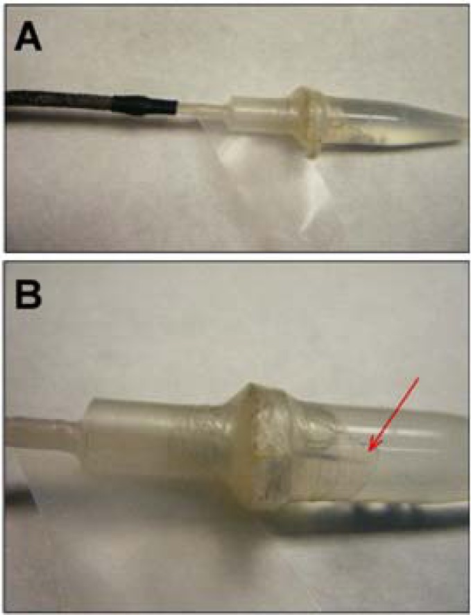
We have designed probe holders that can be filled with deionized HPLC-quality water to keep the newly-constructed probes moist and protected prior to experimentation. Of course it is important that all epoxy is cured prior to using these probe holders. These holders have withstood the tests of time, are easy to make, and maintain their function over extended periods of re-use. They are made from clear 1.5 ml clear plastic centrifuge tubes with snap-top lids, the wide end of a 1.0 ml plastic disposable micropipette tip, and sealed with a short 2-cm strip of Parafilm. Simply cut off the wide end (part that grips around an adjustable micropipette device) of a plastic disposable tip. The best micropipette tips for this are those that are rather smooth on the outside as these will allow a better Parafilm seal. Drill a hole in the lid of the centrifuge tube that is just wider than the outer diameter of the connector assembly end (see Figure 2B). Be sure to clean any small bits of plastic away. Then cut off the top portion of a plastic micropipette tip with a straight razor blade keeping the cut as perpendicular to the tip length as possible. It may be helpful to lightly heat the cut end with a lighter flame and then press that end onto a cool flat surface to ensure a flat cut. Using modeling plastic cement applied around the edge of the cut (keeping it mostly on the outside) join the cut pipette end with the centrifuge tube lid so that the pipette tip end surrounds the drilled hole. If the lid is closed when you do this, it is possible to clamp the centrifuge tube upright during the drying process. Once completely dry, make sure the original hole drilled in the centrifuge tube was not blocked or changed by testing with an unused connector assembly end that should easy insert now through both the pipette tip back end and the hole in the lid. If it does not, it should be possible to unsnap the lid on the centrifuge tube and sand the edge of the hole until the connector assembly fits through. Clean this unit and snap the lid shut again. Make narrow strips (half cm in width) of Parafilm and wrap these around the outside of the union between the cut pipette tip and the centrifuge tube being sure to stretch the Parafilm while wrapping and going both under and over the centrifuge tube lid lip to secure this union. Fill the centrifuge tube with deionized HPLC-quality water and insert a finished probe tip so that the membrane tip is submerged in the water. Then wrap a thin (2-cm) strip of Parafilm around the top to both seal the water in and hold the probe in place. We then hang these probes in the refrigerator so they hang through the grating of the shelf until use (see Figure 20 below for finished product).
Figure 20.
Probe holders created from small 1.5 ml centrifuge tubes. Red arrow in B points to probe membrane tip inside holder. Parafilm wrap keeps water sealed in and probes can hang in refrigerator.
Adding Flex to the Connector Assembly
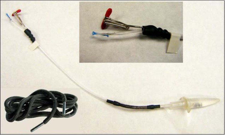
Our experiments called for microdialysis inside mouse operant chambers and we found it useful to modify the standard connector assembly tubing slightly because it was necessary to provide both ease of movement and connector length while mice conduct learned behaviors in such conditions. The standard connector assembly is made of rather stiff plastic tubing which works fine while animals are in open field or microdialysis bowl conditions, but it was apparent that they were causing unwanted postural deviations during operant experiments. While another way to accomplish this same correction might have been to engineer a different sort of weighted balance arm for these chambers, we feel our solution more than met our needs. To accomplish this, cut a small section (approximately 7.0 cm) from the length of connector assembly tubing starting about 3.0 cm from the guide cannula-connecting end. Then acquire a woven boot shoelace from a local shoe or department store (such as Figure 21). Cut a section of the shoelace that is approximately 2 cm longer than the section removed from the connector assembly (being sure not to include the tipped ends). Inside these boot shoelaces you will find several strands of reinforcement strings that you will need to remove leaving only the woven tube. Remove these strands by grasping them with tweezers and simply pulling them straight out. Cut two 2-cm lengths of 3/16” (4.8mm diameter) heat-shrink tubing (available from any hardware store) and place these onto the cut ends of the connector assembly that remained after you removed the small section and slide them out of the way. Then place some gel superglue onto the outside of the cut ends of connector assembly about half a centimeter back from the end, and insert these ends into each end of the emptied boot shoelace so that the connector assembly tubing travels inside about 1-cm for each end (such that the superglue can bind with the shoelace on the inside). Twirl these inserted ends between (gloved) thumb and forefinger for at least 30 seconds while the superglue dries to hold. Then slide the shrink tubing down over the glued ends of shoelace on either side so that 1cm is over the shoelace and the other over only connector assembly tubing. Heat the shrink tubing carefully, ideally with a tight heat source such as a small flame, so as not to melt the connector assembly tubing or burn the shoelace. Twirl the whole apparatus around so that the heat is applied evenly all around the shrink tubing and it shrinks down evenly around the outside of the glued shoelace ends. The PE-10 tubing will fit through this fairly easily, with only slight wiggling. If low-torque fluid swivels are used for the microdialysis session, these shoelaces should hold nicely with no twisting. If the shoelaces do twist, some resistance can be added prior to its incorporation on the connector assembly by painting the shoelace with a thin coat of clear fingernail polish, allowing it to dry, and bending it back and forth afterwards until the desired flexibility is achieved.
Figure 21.
Image depicts whole probe assembly with probe in holder and added flex section as described. Inserts depict probe “T” connector made by attaching a bent paperclip to the top of probe assembly using shrink-tubing. Below left depicts the type of boot shoelace used for flex section creation. The “T” connector is only necessary as a means to attach the whole probe assembly as shown in Figure 18 and is made from a large “jumbo” paper clip.
PEDAGOGICAL REMARKS
We recommend training students in a stepwise manner so that each probe construction step is mastered before the next is attempted. During the learning curve, we have discovered that students retain the skills better if they face the challenge of teaching the next group each skill. Using this strategy ensures that students discover their limitations without compromising the quality of the final probe, given many of the techniques require steady hands and patience with working in small and magnified environments. Students can learn skills they excel at and apply those while working to master the other skills. Initial one-on-one work with students to describe and demonstrate the goals of each step can generate valuable returns. The more students working in the lab, the more easily overall procedures can be split up between students using an assembly-line approach. After completing a probe, a good test of any student’s overall probe-construction is to test the probe in question for both flow and using a standard invitro testing procedure to determine probe recovery for your compound of interest. The probe quality can then be used as a standard measurement as part of an assessment protocol. Leaks at various places can be found, and if they are possible to resolve, you or one of the resident student experts can demonstrate how prior to experimentation.
If students attend to these steps on a timely basis, they typically become proficient in about two weeks, after repeating the full construction process about two to three times. It has also become clear that watching others who are skilled in the process accomplish each step helps tremendously. Many skills tend to require certain finger positioning that is easier to model than to learn solely by trial and error. The most efficient strategy to promote is accomplishing one step each day or two (separated by epoxy hardening time). This process gives them ownership to develop a working probe as they will be accountable for it when tested and it also teaches them why each step and the technique involved is so critical. Nothing teaches a student about care at critical epoxy application stages better than a probe that leaks or doesn’t flow after construction is finalized.
While problems with these probes are rare, there are some that are easily determined with a checklist of diagnostic checks. All connection joints need to be checked if mobile phase (aCSF) is not flowing from the output line, at all, or at the same pace or volume as the input feed. The most obvious connections to check are the connector adaptors, though a leak at the input connector (at the syringe pump connection) typically means there is a blockage in the lines somewhere impeding flow. Leaking at any of the epoxy joints means that joint was not successfully sealed, typically because epoxy was not allowed to enter the inside of tubing surrounding the fused silica or because the sanding-roughing of tubing step was skipped at Steps one or three. Knowing where epoxy joints are in the constructed probe should lead students to look there as part of the diagnostic process. Leaks could come around the friction fitting with the infusion cannula and PE-50 tubing. Leaks around the membrane tip can be easily seen by pumping fluid through the probe and looking directly at the probe tip. No solution should accumulate at this tip if it is intact.
Inserting probes into an awake animal can sometimes be tricky as the animal’s head will need to be held steady. When students learn to do this, they should first practice holding the animal properly and familiarize themselves with this. Damage to the probe tip can easily occur during the insertion process if the membrane scrapes on the metal edge prior to full insertion. If leaking then occurs from the membrane inside the brain, this typically leads to an immediate cessation of output flow, and this should inform the experimenter to immediately remove the probe and replace it with an intact probe. A checklist of various places to check when there are various problems can be very useful to keep experiments going smoothly while students take the reins.
Following experiments, distilled HPLC-quality water should be pumped through the probe after removal from the animal to clear out any remaining mobile-phase salts from the tubing. This can be done overnight, and the probes can be collected the following day for recycling. The infusion cannulae can be removed from each of these used probes, and it is typically most efficient to push a small quantity of pure ethanol through the remaining tubing (both input and output lines) first before pushing air through. To push air through the lines, attach air-filled syringes to both input and output connectors and dip the end into a beaker of pure ethanol. Continue to push air through until only air bubbles issue from the input and output ends. Remove from the ethanol and dry with a clean paper towel or Kimwipe and allow this tubing skeleton to air dry until there is no sign of liquid at the end with the silica. Then proceed with replacing the membrane as described above under Step six.
Thus far since the Sandstrom Lab began in Spring 2004, eighteen undergraduate students have been involved in our lab learning to produce microdialysis probes and perform experiments. These students were either volunteers or taking directed research courses. Titles of posters produced from these efforts are listed (see asterisks) within the reference list. Thus far we have produced three posters for Society for Neuroscience annual meetings and six posters for our annual university research event – the Student Research and Creative Endeavors Exhibition (Central Michigan University Office of Research and Sponsored Programs event). These projects have all involved microdialysis with freely moving rats or mice utilizing student-generated microdialysis probes to measure glutamate and gamma amino butyric acid, or dopamine, serotonin, norepinephrine, and monoamine metabolites.
REFERENCES
- Benveniste H, Hüttemeier PC. Microdialysis--theory and application. Prog Neurobiol. 1990;35:195–215. doi: 10.1016/0301-0082(90)90027-e. [DOI] [PubMed] [Google Scholar]
- *Ferris A, Fuller J, Gustavision Z, Hummon C, Morris M, Sobczak J, Strawsine M, Vogl L, Sandstrom M. Exploring environmentally stimulated neurochemical responses in a mouse model of Huntington’s disease using microdialysis. Student Research & Creative Endeavors. 2005:12. [Google Scholar]
- *Goffus A, Bocek K, Carrasco A, deLafe M, Maas T, Santini A, Sandstrom M. Measuring striatal neurochemical responses to pre-pulse inhibition in a mouse model of Huntington’s disease. Student Research & Creative Endeavors. 2006:13. [Google Scholar]
- Jolly D, Vezina P. In vivo microdialysis in the rat: low cost and low labor construction of a small diameter, removable, concentric-style microdialysis probe system. J Neurosci Methods. 1996;68:259–267. doi: 10.1016/0165-0270(96)00089-1. [DOI] [PubMed] [Google Scholar]
- *Larder A, Askew J, Cooper C, Elam E, Hoskins P, Steffes S, Sandstrom M. Neurochemical changes within the amygdala and striatum related to acoustic startle and pre-pulse inhibition experiences in freely moving R6/2 mice. Student Research & Creative Endeavors. 2007:14. [Google Scholar]
- *Lupo M, Carrasco A, Combs M, Galinac A, Pearsall K, Steffes S, Storai K, Sandstrom M. Monoaminergic contributions to perseveration among R6/2 mouse models of early Huntington’s disease engaged in operant tasks of differential complexity. Student Research & Creative Endeavors. 2008:15. [Google Scholar]
- Medline Advanced Search initiated 6/19/08 at http://www.ncbi.nlm.nih.gov/sites/entrez?db=pubmed using simple keyword search “microdialysis” at each corresponding year. Medline records are cumulative from 1966 but microdialysis articles began to appear in 1979.
- *Palmer S, Carrasco A, Combs M, Gallinac D, Kraynak S, Lupo M, Steffes S, Sandstrom M. Comparing neurochemical responses to sex-related odors between two mouse models of Huntington’s disease. Student Research & Creative Endeavors. 2008:15. [Google Scholar]
- Pettit HO, Justice JB. Procedures for microdialysis with small bore HPLC. In: Robinson TE, Justice JB, editors. Microdialysis in the neurosciences. Amsterdam: Elsevier Health Sciences; 1991. pp. 117–153. [Google Scholar]
- Robinson TE, Justice JB. Microdialysis in the Neurosciences. Amsterdam: Elsevier Health Sciences; 1991. p. vi. [Google Scholar]
- Robinson JE. Microdialysis: A novel tool for research in the reproductive system. Biol Reprod. 1995;52:237–245. doi: 10.1095/biolreprod52.2.237. [DOI] [PubMed] [Google Scholar]
- *Sandstrom M, Boček K, Carrasco A, deLaFe M, Goffus AM, Santini A. Striatal glutamate release responses to startling noise pulses are not as suppressed by pre-pulses among R6/2 transgenic Huntington’s model mice as they are among wild type littermates. Society for Neuroscience Abstracts. 2006;32 [Google Scholar]
- *Sandstrom M, Steffes S, Carrasco A, Lupo M, Lee J, Buxton T. Measuring striatal monoamine changes in R6/2 transgenic mice during an operant task designed to challenge behavioral flexibility. Society for Neuroscience Abstracts. 2008;34 [Google Scholar]
- *Sandstrom M, Strawsine M, Ferris A, Gustavision Z, Devos CK, Goffus AM. Glutamate and gamma-aminobutyric acid microdialysis measurements from striatum of freely moving R6/2 transgenic mice in response to ambient light manipulation. Society for Neuroscience Abstracts. 2005;31 [Google Scholar]
- Sandstrom MI, Rebec GV. Extracellular ascorbate modulates glutamate dynamics: Role of behavioral activation. BMC Neurosci. 2007;8:32. doi: 10.1186/1471-2202-8-32. ( http://www.biomedcentral.com/1471-2202/8/32). [DOI] [PMC free article] [PubMed] [Google Scholar]
- Tisdall MM, Smith M. Cerebral microdialysis: research technique or clinical tool. Br J Anaesth. 2006;97:18–25. doi: 10.1093/bja/ael109. [DOI] [PubMed] [Google Scholar]
- *Vogl L, Carrasco A, deLafe M, Devos C, Goffus A, Sietsma Z, Strawsine M, Vue M, Sandstrom M. Dopaminergic control of neostriatal GABA release in rats depleted of nigrostriatal dopamine as weanlings. Student Research & Creative Endeavors. 2006;13 [Google Scholar]


