
Figure 8. Flowchart of the diagnostic setup.
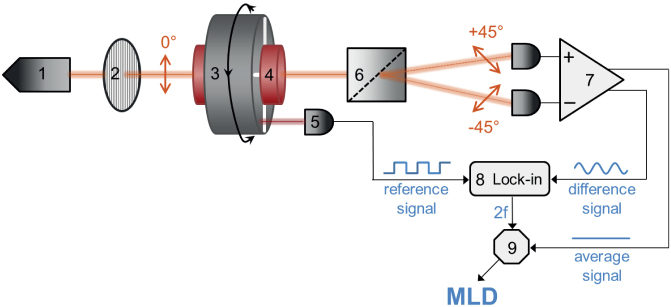
The beam from the laser diode (1) passes through a polarizer (2) and becomes vertically polarized. Then it goes through the sample holder (4) located in the bore of the Halbach magnet (3). The magnet is rotated with a frequency f by a d.c. motor, thus, the uniform magnetic field of B ≈ 1 T at the sample position rotates within the plane perpendicular to the light propagation. After the sample, the beam is divided into two parts with orthogonal polarizations (±45°) by a Rochon prism (6). The difference and the average of their intensities are detected by a balanced photodiode bridge (7). The 2f component of the difference signal is filtered out by a lock-in amplifier (8) using the reference signal from an optoswitch (5) monitoring the rotation of the magnet. To obtain the MLD signal, the amplitude of the second harmonic (2f) signal is normalized with the average signal by a divisor (9).