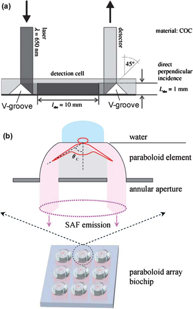
Fig. 7.
(a) Detection cell integrated in a CD device with an increased optical path length. The incident optical beam was guided by the V-groove on the left, through the detection cell, and reflected by the V-groove on the right before being detected. V-grooves were created from the bottom surface of the device. Courtesy of Dr. Jens Ducrée (ref. 109). (b) Layout of a 3 × 3 COC array with paraboloid wells. Shown above the array is an exploded view of a well with supercritical angle fluorescence (SAF) emission. Courtesy of Dr. Colette McDonagh (ref. 111).

