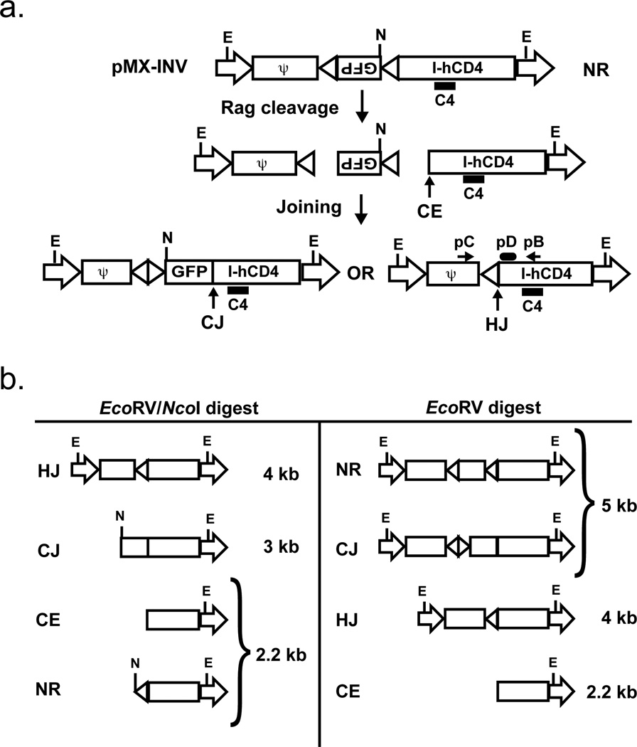
Figure 1. Schematic of pMX-INV and rearrangement products.
a. Schematic showing the non-rearranged (NR), coding joined (CJ) and hybrid joined (HJ) configurations of the pMX-INV retroviral recombination substrate. The IRES-human CD4 cDNA, the GFP cDNA and the recombination signals (triangles) are shown. The relative positions of the EcoRV (E) and NcoI (N) restriction sites are shown. Also indicated is the 3’ coding end (CE) generated by Rag cleavage. The relative positions of the pC and pB oligonucleotide primers used to amplify hybrid joints are shown, as is the pD oligonucleotide used to probe these PCR products. The relative position of the C4 probe used for Southern blot analysis is also shown. b. Schematic of the different C4 probing DNA fragments generated by digestion of pMX-INV in different configurations (NR, CJ, HJ and CE) with EcoRV or EcoRV/NcoI.

