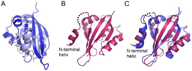
Figure 6. N-terminal helices in channel PAS domain structures.

a) View of N-terminal helix (light blue) packed against hydrophobic patch of dELK PAS domain. Residues forming the patch are shown as stick. b) View of Δ9-hERG PAS structure with N-terminal helix packed against the β-sheet. Dotted line represent a possible linker connection between N-terminal helix and the body of the Δ9-hERG PAS domain. c) Superposition of structures of Δ9-hERG PAS (redbrick) and dELK (blue). N-terminal helices are indicated. Dotted line as in b).
