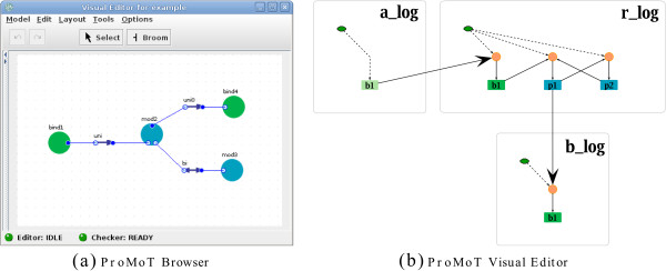
Figure 10.

Implementation of the PIM concept. In (a) the PIM of the small example depicted in Figure 4 is shown in the ProMoT Visual Editor. Green circles denote binding processes; blue circles denote modification processes. In (b) the modular logical model derived from the PIM in (a) is shown. The ProMoT Visual Explorer facilitates sophisticated graphical representations of logical models. Green and blue filled rounded rectangles represent the processes occurring on the sites of molecules; light green rounded rectangles represent binding sites which do not correspond to a process. Orange circles depict the logical functions connecting the incoming edges to the nodes. As described above, these logical functions are determined by the parameter tables. The small green nodes (with hexagonal shape) connected to the logical functions depict the basal activity of molecules. The module borders are represented by gray rounded rectangles around the nodes belonging to one molecule.
