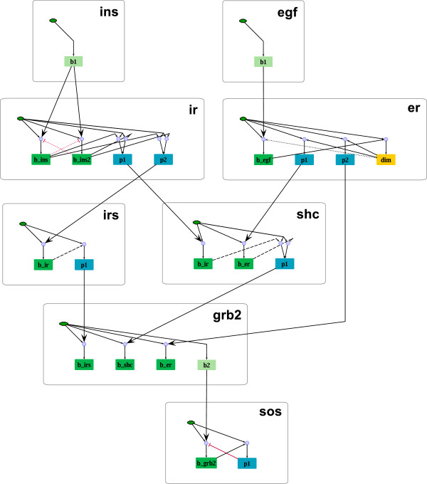
Figure 13.
Site-specific logical model derived from the PIM in Figure12. Nodes representing the basal activity of a molecule are depicted as green hexagons. Blue rounded rectangles stand for nodes corresponding to phosphorylation sites. Dimerization sites are depicted in yellow. Nodes representing binding sites of the respective molecule are depicted as green (if the L-node corresponds to a unique P-node, that is, to a binding process in the PIM) and light green filled rounded rectangles (if the L-node corresponds to a unique L-node; see section “A PIM makes the logic of rule-based models transparent”). Three model variants are illustrated: Model Mdown contains all solid arrows, model M contains all solid and dashed arrows and model Mup contains all arrows (solid, dashed and dotted). For all three model variants blue circles symbolize AND gates and all incoming edges to a node are by default connected by OR. Black arrows indicate activating, red blunt-ended lines inhibiting influences. As described above, the logical functions have been derived from the parameter tables (see Additional file 1). The module borders are visualized by gray rounded rectangles. The visualization has been created in ProMoT.

